Chastising in the same vein as Mark's: read the documentation first, then ask; build it; share the results!
🙂
🙂
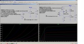
I got curious about how LU behaves in cascode and reread Pa's Cascode Article
The LU model I'm using, models the triode region pretty well.
Sim looks like what I traced, only difference was slightly higher Vgs needed to get sim look like scope.
I drew lines where Pa recommended LU operating area in cascode. He explains in article well. See, you don't let it get to that pentode area.
I'll build the cascode module and trace curves for sanity check.... eventually... I wish it were in a TO-220 package.🙄
Thanks lhquam for links to Pa's explainations of Zen v9/F4. You got my wheels turning on triode in cascode. Learning a bit more. 😀
My fav amp these days is this cascode module with coil as current source, will start a thread about it someday.
Attachments
I have run some "interesting" simulations of a variant the LuDEF output stage in order to get a better understanding of the behavior of the cascoded JFET.
Nelson's post in Pass JFET Power Amplifier says:
The result is to minimize (or adjust) the level of the 2nd harmonic. What I observe is that the technique is also adjusting the slope of the load line on the JFET, which is the apparent load impedance on the drain of the JFET.
The mu-follower "gain" resistor has similar behavior of changing the slope of the load line, increasing mu-gain increases the apparent load impedance on the drain of the JFET.
Nelson's post in Pass JFET Power Amplifier says:
In any case, The idea is that the gain of the device increases
with current, and increases with voltage. Ideally we want the
gain to be constant, which would make it distortionless. So
when we examine the voltage/current load line of a linear
amplifier, we see that for a resistive load the voltage across
the device decreases as the current increases, and so by
choosing the load line carefully, we have an opportunity to
cancel some nonlinearity in the gain device. This technique
appears to be most popular with triodes.
The result is to minimize (or adjust) the level of the 2nd harmonic. What I observe is that the technique is also adjusting the slope of the load line on the JFET, which is the apparent load impedance on the drain of the JFET.
The mu-follower "gain" resistor has similar behavior of changing the slope of the load line, increasing mu-gain increases the apparent load impedance on the drain of the JFET.
I got curious about how LU behaves in cascode and reread Pa's Cascode Article
The LU model I'm using, models the triode region pretty well.
Sim looks like what I traced, only difference was slightly higher Vgs needed to get sim look like scope.
I drew lines where Pa recommended LU operating area in cascode. He explains in article well. See, you don't let it get to that pentode area.
I'll build the cascode module and trace curves for sanity check.... eventually... I wish it were in a TO-220 package.🙄
Thanks lhquam for links to Pa's explainations of Zen v9/F4. You got my wheels turning on triode in cascode. Learning a bit more. 😀
My fav amp these days is this cascode module with coil as current source, will start a thread about it someday.
Can you post your Lu1014D Spice model? I am using the one from Lovoltech, but I suspect that it isn't good at the 1.5A region of operation. The transconductance values I see in simulations are high, like 40S. I do not have parts to measure. Do you have parts and can measure transconductance?
Can you post your Lu1014D Spice model? I am using the one from Lovoltech, but I suspect that it isn't good at the 1.5A region of operation. The transconductance values I see in simulations are high, like 40S. I do not have parts to measure. Do you have parts and can measure transconductance?
I have two pairs from an old F3 that was not built. I was planning on an F3 until the LuDEF popped up.
Happy to send them to you for testing. I think the LuDEF kits will come with them. I’m in Portland.
Here's the spice model. That one from Lovoltech didn't work for me either. 
.SUBCKT LU1014 1 2 3 ; D G S
+ PARAMS: a=21.7924 b=4.5599 c=10.2887 d=9.1318 e=61.579
+ f=0.5726 g=-16.0443 h=71.8659
G1 1 3 Value={(a+b*V(1,3))*(1-V(2,3)/
+ (c+d*V(1,3)))**(g+h*V(2,3))*TANH((e*V(1,3))/
+ (a*(1-f*V(2,3))))}
.ENDS LU1014
.SUBCKT LU1014 1 2 3 ; D G S
+ PARAMS: a=21.7924 b=4.5599 c=10.2887 d=9.1318 e=61.579
+ f=0.5726 g=-16.0443 h=71.8659
G1 1 3 Value={(a+b*V(1,3))*(1-V(2,3)/
+ (c+d*V(1,3)))**(g+h*V(2,3))*TANH((e*V(1,3))/
+ (a*(1-f*V(2,3))))}
.ENDS LU1014
Attachments
not disputing importance of investigation , but nature of cascoded triode wasn't puzzle by itself from start ...... I mean - not start of making LuDEF, but from start of time
probably somewhere right after God made a Wheel and Quarter window for car, Man deliberately invented triode ..... then accidentally made Penthode
I mean , things are pretty clear when you draw constant voltage line on triode U-I graph, which means you're back in penthode territory, luckily still having some benefits of lower Ri
anyway, I didn't spent any time exploring varieties of triode cascoding while making LuDEF ( did that years ago, when I had Ikebana F3 on plank in my workshop), exploring various amounts of cascode modulation, how Pa explained it in article
and frankly - can't remember much details, except conclusion that Pa made it spot on, at least I couldn't set it better to my ears
when I started with LuDEF, decided from start that LU cell is not going to have any amount of modulation made by me, pretty much getting some action from mosfet side - directly seeing Ugs variation of mosfet itself
small yes, changing that easy if I introduce source resistor which I didn't want......... much more complicated in any other way
and when I got first preliminary measurements, didn't even think further about cascode modulation
Here's the spice model. That one from Lovoltech didn't work for me either.
...
- I tried your model and I am finding the transconductance of the cascoded JFET to be about the same as the IRFP9140.
- With the Loveltech model the JFET gm is about 10X higher than the IRFP9140.
- ZM's simulation show a JFET gm about 2X higher than that of the IRFP9140.
It appears that everyone has a differeny SPICE model for the Lu1014.
ZM: Can you measure the AC voltages across the output MOSFET drain sense resistors R131 and R129? Test at something like 1 Watt, 1kHz, or lower frequency that you multimeter can accurately measure.
schematic and final specimen, on which all measurements are made - IRFP9140
sims with Cordell's IRFP9240 ( floating around as IRFP9240C)
sims with Cordell's IRFP9240 ( floating around as IRFP9240C)
ZM: Can you measure the AC voltages across the output MOSFET drain sense resistors R131 and R129? Test at something like 1 Watt, 1kHz, or lower frequency that you multimeter can accurately measure.
sorry, moved LuDEF from T-Bed, so can't do any measurements in shorter time than a week or so
either to make second T-Bed or to find case for it 🙂
T-Bed in this moment singing with Old Soul, burning in, me smiling twice around head
Run a Vgs-Id curve on the LU1014 at 3.7v Vds. That is how it will behave cascoded in your LUDEF as long as Vds remains at 3.7v.
Hi ZM,
Would it be ok with you if I made my own layout of just the LuDEF output stage so I can try with different input stages? This will be open source for DIYA (will not be used for any commercial stuff) and all Gerber files will be posted back to this thread for all to use.
Thanks,
X
Would it be ok with you if I made my own layout of just the LuDEF output stage so I can try with different input stages? This will be open source for DIYA (will not be used for any commercial stuff) and all Gerber files will be posted back to this thread for all to use.
Thanks,
X
Run a Vgs-Id curve on the LU1014 at 3.7v Vds. That is how it will behave cascoded in your LUDEF as long as Vds remains at 3.7v.
Here is what I get using the LU1014 model from Cinco. (RsM1 is 10^-6R, ie. shorted).
Attachments
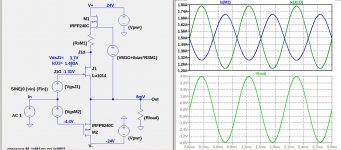
Run a Vgs-Id curve on the LU1014 at 3.7v Vds. That is how it will behave cascoded in your LUDEF as long as Vds remains at 3.7v.
I'm keeping LU Uds at 2V4; was thinking of varying, but - considering that I chose 1A5 for Iq, chickened 🙂 ....... in fact , was satisfied with measurements so didn't found any reason to stress little one more
Hi ZM,
Would it be ok with you if I made my own layout of just the LuDEF output stage so I can try with different input stages? This will be open source for DIYA (will not be used for any commercial stuff) and all Gerber files will be posted back to this thread for all to use.
Thanks,
X
be my guest ..... 🙂
Here is what I get using the LU1014 model from Cinco. (RsM1 is 10^-6R, ie. shorted).
little later** I'll collect all LU files for sim and zip it here
** (now I need to invest some time in homework .... you know - kids these days schooling online, and that seems much more work than in normal way ..... so, she's practicing Piano, and Pa is helping a little)
- Home
- Amplifiers
- Pass Labs
- LuDEF