In my case it's the J310 CCS which drifts so much.
I sprayed some Isopropanol on top of them ( cooling them down) and offset goes sky high to about 700mV. Spray it on the other CCS and offset to -600mV. So coupling them seems wise...
The BC560 and 550 do react also, but only 10 - 20mV by cooling.
Or maybe put a NTC or PTC in the CCS....must have more thought of that....😀
How much Current change in the 310 CCS is needed for that 700mV of output offset?
It may be that the 310 is not working as a CCS, i.e. not in constant current mode.
Vds > 2Vp for a working jFET. For a damaged jFET, it just won't work as a CCS.
Did you measure and keep a note of Vp for your jFETs?
It may be that the 310 is not working as a CCS, i.e. not in constant current mode.
Vds > 2Vp for a working jFET. For a damaged jFET, it just won't work as a CCS.
Did you measure and keep a note of Vp for your jFETs?
Last edited:
andrew, maybe also that the jfet is running hot? maybe it s normal a thermal shock that dramatic could have such an impact, with sufficiently high value output I/V resitor?
Last edited:
There is around 2.5 Volt over the current source, current source is delivering 23 mA.
J310 is not running hot.
Last night I thermally coupled both CCS JFETs, wow, that solves it! Still learning....
Now offset wanders just a few mV. No big changes in offset when I blow a little air over it.
Only issue is that when room temperature varies, because of sun shining in my room offset wanders slowly +20 a 30 mV. When I re adjust with the potmeter it is good.
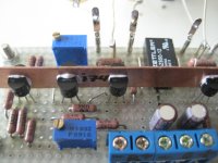
With this new insights I am going to build it all over again and want to do the thermal coupling "CheffDeGaar UGS3, 4" style with all the devices.
But this brings me to the theoretical question: Is it better to couple all the devices with a big chunk of metal ( like CheffDeGaar did) or use minimal metal so the devices really 'see' each other and respond to each other?
But this brings me to the theoretical question: Is it better to couple all the devices with a big chunk of metal ( like CheffDeGaar did) or use minimal metal so the devices really 'see' each other and respond to each other?
True!
But I was thinking very minimal....Cu strip 0.5mm thick with dimensions: 90 x 10mm? LxH
Glue the device both sides with thermal glue to it.
But I was thinking very minimal....Cu strip 0.5mm thick with dimensions: 90 x 10mm? LxH
Glue the device both sides with thermal glue to it.

One more thing - I forgot to post the version with k246/j103. The buffer on the output is obligatory here.
Hi Juma,can I use the 2SK246/J103 GR version for the input device and replace BC550C/BC560C due to we have this parts in my hand.thanks.
Thanks Juma!
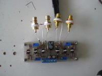
This little amp sounds lovely, almost as transparent as the DCB1 and gives me just about 13 dB extra gain which is sometimes needed for high resolution audio recordings.
With the relais I can switch the BAF2013 in en out the signalpath when needed.
Offset is still a small problem, the last picture is giving me the best results. Varies between 0 - 20 mV.
If the BAF2013 is in the final enclosure I will decide if I put an output capacitor after it, or not.
Attachments

Simple CCS gives more offset drift than just a resistor but it uses less PS voltage (and still doesn't sound better). Anyway it can be dealt with offset drift in so many ways - almost anything will influence it. You can play with it or use a small cap between the gain stage and the buffer (47 - 100nF suffices with buffer's Zin of 1Meg). I routinely use 100nF WIMA MKP10 without influence on the sound. Buffer alone has offset drift of +/- 1mV so problem solved...

In my case it's the J310 CCS which drifts so much.
I sprayed some Isopropanol on top of them ( cooling them down) and offset goes sky high to about 700mV. Spray it on the other CCS and offset to -600mV. So coupling them seems wise...
The BC560 and 550 do react also, but only 10 - 20mV by cooling.
Or maybe put a NTC or PTC in the CCS....must have more thought of that....😀
Walter you solved the offset issue but if you look at datasheet you`ll see that J310 do not work as a CCS at such low Vds voltages especially at such a high current, BUT there`s a little Vds voltage change in this case so it does`t matter as much. You could try bc5xx/led ccs, maybe would be better sounding, but you made the whole thing, so enjoy! 🙂
I think you are right...did some testing with the CCS:
Vds (V) Iccs (mA) 2 21.4 2.5 23.6 3 24.7 4 25.6 5 26.0 6 26.0 7 26.1 8 26.1 9 26.1 10 26.2
Between 5 to 10 Volts the CCS is working correctly. So if I raise the rail voltages to 12.5 - 17.5 Volts I'm OK?
Juma said Vout = around 7Vpp with the 10 Volts rails, so this will become higher also...that's a good thing....🙂
Only downside is that I can't use the DCB1 rails and have to build a separate PSU😡
Oeps no excel, so .jpg
Attachments

Last edited:
It`s up to you, you have a few possibilities. 2SK246BL it`s perfect for low voltage ccs, if you can find it the, but the Idss is much lower.
You have very little voltage variation over J310 ccs so this is not a DC issue. I wonder what is their AC impedance...
BTW Juma said ccs doesn`t sound better then resistors. Did you used hem for better PSRR or lower distortion?
You have very little voltage variation over J310 ccs so this is not a DC issue. I wonder what is their AC impedance...
BTW Juma said ccs doesn`t sound better then resistors. Did you used hem for better PSRR or lower distortion?
Hahaha, no just lazy and following Juma's schematic in the Mesmerize thread: http://www.diyaudio.com/forums/pass-labs/176723-mezmerize-dcb1-building-thread-112.html#post3778938 😀
- Home
- Amplifiers
- Pass Labs
- LSK pre - BAF 2013