You next need to measure the primary inductance, my guess its going to be over 100H - can your LCR go that high? Best measure at 1kHz for both shorted and un-shorted.
3.7H 100Hz I'm sorry mine Wavetek LCR55 only measures 20H to 200H 100Hz accuracy +-5%
Last edited:
236-237mH secondary shorted.
236-237mH secondary shorted 1kHz accuracy +-3%
Mine LCR measures with different frequencies:
200uH to 2H 1kHz
20H to 200H 100Hz
Accuracy:
2mH to 200mH +-3%
2H to 200H +-5%
Last edited:
Since I can't make any sense of a reading of 3.7H for the primary inductance, best proceed with the 'suck it and see' route. Based on your specs above, you can't measure above 2H with a 1kHz stimulus anyway.
Measured two new txs
163.7uH secondary shorted
10.32H primary open
176.7uH secondary shorted
10.25H primary open
I'm sorry primary opens measurements are Henries
163.7uH secondary shorted
10.32H primary open
176.7uH secondary shorted
10.25H primary open
I'm sorry primary opens measurements are Henries
Last edited:
In order to get the best values for R and C we'd need to know the leakage inductance of the transformer. Since that's not shown in the Sowter datasheet you could either measure it (needs an inductance meter) or you could just try 680ohm and 100nF and see what happens.
What have I to look after putting 680ohm and 100nF in the secondary? I guess using my scope, but what have I to look for and what scope scales?
A squarewave stimulus would be best - say 1kHz. Look for how much overshoot you get when the load is connected as well as the RC.
By ear - if it sounds too bright, decrease the R. Too dull, increase R.

A squarewave stimulus would be best - say 1kHz. Look for how much overshoot you get when the load is connected as well as the RC.
I will use a dummy load of 100K at the secondary because all my preamps have 100K input impedance
N.B. I sent an email to Sowter asking the leakage inductance.
Good idea with the 100k dummy load.
To run the trafo in the sim you need figures for both primary inductance and leakage inductance. Oh and also the DCR of both windings.
To run the trafo in the sim you need figures for both primary inductance and leakage inductance. Oh and also the DCR of both windings.
Asked the information to Sowter. Now time to play with the scope looking for the best squarewave @ 1kHz, thanks abraxalito.
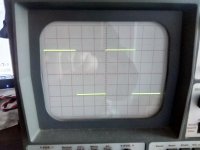
Attached pics of scope, one direct to SG and the other to the 100K dummy load, finally resistor 3k61 so I will use standard resistor 3K6.
It's necessary the output coupling capacitor after the 1:1 transformer?
It's magic, no cliks or pops changing between PCM & DSD. I still need the output capacitor to avoid DC: I have AVC at the input of preamp or headphone amp and don't likes DC, I listen scratches when I turn the volume.
Attachments
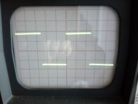
Very clean looking squarewave, nice job! I don't think you need a capacitor after the trafo but certainly it needs one before it. Its impossible for DC to come out from a trafo.
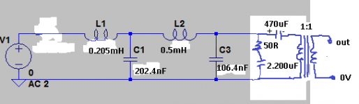
Incidentally, 10uF is too low for a 600ohm trafo, I think you'd better go up to at least 470uF.
Incidentally, 10uF is too low for a 600ohm trafo, I think you'd better go up to at least 470uF.
As attached schematic? I have non polar and polar both 63V what's the best in this application? if it's polar + connected to the filter and - to 1:1 tx, right?
I'd use a polar cap, as you say + side to filter, - to trafo. No need for 63V, 6.3V would do fine.
Forgot to attach the schematic.
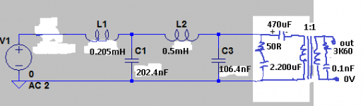
Finally used two caps 220uF 16V BG. Always can increase capacitance adding one more 220UF 16V in parallel.
Finally used two caps 220uF 16V BG. Always can increase capacitance adding one more 220UF 16V in parallel.
Attachments
Last edited:
The primary inductance of the trafo forms a resonance with the coupling cap. A high enough value cap keeps the resonance well below audio frequencies. If you decrease the cap you'll move the resonance (a bump in the FR) upwards in freq so will end up with more bass. If you keep reducing the cap the bump will move into the mid range eventually and the bass will roll off prematurely.
- Home
- Source & Line
- Digital Line Level
- low pass filter for DSD