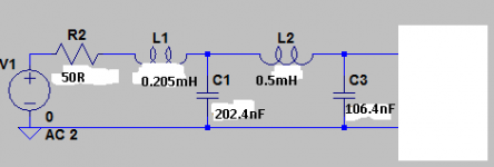
Its still missing - if your source has internal impedance of 50ohm you don't need R2. You should though check that whatever source device is on the Amanero doesn't mind seeing a 50R load.
Last edited:
Yup - what's the power supply for the output device on the Amanero? If its 3.3V then the peak output current will be 66mA - few logic families can deliver that so the output's going to sag.
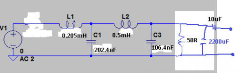
Perhaps better for the output logic device if you AC couple the 50R to 0V with a large electrolytic - 2200uF/6.3V should do fine. We don't need termination all the way down to DC.
I use 10uF 200V MKP Auricap to DC blocking, is enough? or you mind in parallel with 50R load resistor?
Attachments
Last edited:
No, I mean in series with the load resistor. I don't know if 10uF is enough, simulation will tell.
No, I mean in series with the load resistor. I don't know if 10uF is enough, simulation will tell.
I'm sorry I don't know how to use simulator.
No, I mean in series with the load resistor. I don't know if 10uF is enough, simulation will tell.
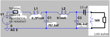
With 10 uF somewhere in between a 50 ohm source and a 50 ohm load, the AC coupling time constant is 10 uF * (50 ohm + 50 ohm) = 1 ms, giving you a first-order roll-off below 159 Hz. I'm neglecting the impact of the other filter components now, but I think that's OK as they presumably only kick in above 20 kHz.
Its as I said before - 2200uF in series with the 50ohm but no need to have it in the signal path as in @MarcelvdG's drawing, rather put it between the 50ohm resistor and 0V.
If you prefer 10uF rather than 2200uF it might work but you're the design authority for that change, not me 😀
If you prefer 10uF rather than 2200uF it might work but you're the design authority for that change, not me 😀
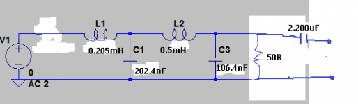
As attached schematic?
What's the purpouse of 2.200uF cap? Dosen't affect the output caracheristics impedance of filter?
What's the purpouse of 2.200uF cap? Dosen't affect the output caracheristics impedance of filter?
Attachments

Last edited:
Yes your schematic looks correct. The 2200uF is in circuit so that there's not a DC current flowing through the 50R resistor which is just wasteful. We still need to terminate the filter at AC (20Hz and up), where the 2200uF looks very low impedance so barely affects the 50R loading.
- Home
- Source & Line
- Digital Line Level
- low pass filter for DSD