Shinga-
Really interesting writeup. With tweaking the Shibasoku can be improved a little but its a lot of work. Most commercial analyzers are limited in THD+N by the input attenuators, something that there is no easy way around.
Your design is quite interesting. You can use an LM339 Quad Comparator as an open collector amp to do the precision 4 phase rectification without the diodes. I don't know if you would get lower distortion but you might.
Thank you for finding the new site. Are you the author?Here is the current flip-flop world
http://flip-flop.world.coocan.jp/
Here is the current flip-flop world
http://flip-flop.world.coocan.jp/
Yes I like the given Notch performance as
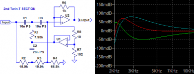
Frequency characteristics: green = first stage, light blue = 2nd stage, red = general)Frequency characteristics: green = first stage, light blue = 2nd stage, red = general)
See performance picture for H2....H10 😎
Attachments
The frequency response is quite amazing. Aren't new harmonics introduced by the feedback op amp (active circuit)?Yes I like the given Notch performance as
Frequency characteristics: green = first stage, light blue = 2nd stage, red = general)Frequency characteristics: green = first stage, light blue = 2nd stage, red = general)
See performance picture for H2....H10 😎
A further problem is the notch depth. It is just ~-25dB if the osc is 1% off. You need a temp oven ...Yes I like the given Notch performance as
Frequency characteristics: green = first stage, light blue = 2nd stage, red = general)Frequency characteristics: green = first stage, light blue = 2nd stage, red = general)
See performance picture for H2....H10 😎
Hi everyone,
I've been reading this thread off and on for possibly years, but everytime looking back at almost 10k posts over 487 pages is really daunting. Searching amounted to nothing really, so please forgive me if i post this and it has been answered before.
So I recaived some time ago one of Victor's oscillators a 1khz sample. I looked around for a suitable power supply, and have, in fact found an interesting design made by Toli (https://tolisdiy.com/2019/03/11/low-thd-oscillator-power-supply-and-pcbs-as-case-panels/).
So I twaeked a bit the Gerber of the PS board - to make it fit the box i had, the circuit is left untouched - and built it.
Now, the problem i see in testing the PS is that without load it measures quite high, 51V, and since Toli told me that it's "tailor made for a specific load"...
the question is, how to simulate Victor's oscillator's load? So I can test the PS before I connect it to my precious device.
Here are some pics.
Switcher datasheet:
1. Output load requirement
To ensure this module can operate efficiently and reliably, the minimum output load may not be less than 10% of the full load during operation. If the actual output power is low, connect a resistor at the output end in parallel to increase the load.
Jan
1. Output load requirement
To ensure this module can operate efficiently and reliably, the minimum output load may not be less than 10% of the full load during operation. If the actual output power is low, connect a resistor at the output end in parallel to increase the load.
Jan
You can test the PSU by strapping a 1K resistor between the Vcc and Vee terminals to simulate the current through the oscillator.
Total resistance between the PDM output terminals would then be 1000 + 6 * 82 = 1492 Ohm, giving the current through the resistor chain of 50/1492 = 33.5 mA.
Then the voltage across the 1K resistor will be 33.5 V, less than 35 V that the oscillator needs but good enough as a PSU test.
I've been running my oscillator for the last eight years from a wallwart PSU that imposes a current of 37 mA through the Victor's regulator.
Regards,
Braca
hello Braca,You can test the PSU by strapping a 1K resistor between the Vcc and Vee terminals to simulate the current through the oscillator.
Total resistance between the PDM output terminals would then be 1000 + 6 * 82 = 1492 Ohm, giving the current through the resistor chain of 50/1492 = 33.5 mA.
Then the voltage across the 1K resistor will be 33.5 V, less than 35 V that the oscillator needs but good enough as a PSU test.
I've been running my oscillator for the last eight years from a wallwart PSU that imposes a current of 37 mA through the Victor's regulator.
Regards,
Braca
I am extremely pleased to say that the voltage drop is 22.732V with a 2w 1K resistor and that once that was tested, I measured 33.501V with Vic's oscillator as a load. Toli's design is very nice and I can't wait to be able to measure it vs a basic linear PS I made with TO92 317/337 (waiting for a QA403)!
For now, I'm very happy!
Hey Jan!
yes, I did look up the data sheet for the PDM2S5D24S too but "connect a resistor" is a bit vague!
Not vague at all! You need at least 10% of the max load current, you know the voltage, Ohms Law tells you the rest.
Jan
Jan
Typically, Vic's oscillator consumes about 25 mA (with input power supply regulator). So, at 35 VDC it is like 35/25 =1.4 kOhm resistor.
Uh the pcb has R7 and R8 as minimum load resistors, with a combined value across Vee and Vcc of 13.6K and I naively thought I had that 10% coveredNot vague at all! You need at least 10% of the max load current, you know the voltage, Ohms Law tells you the rest.
Jan
Not directly concernd about low distortion oscillators, but perhaps of interest nonetheless: classification_of_electrical_oscillators.pdf
The article is a summary and reformulation of the book Oscillators and Oscillator Systems: Classification, Analysis and Synthesis by Jan R. Westra, Chris J. M. Verhoeven, and Arthur van Roermund (Springer, 1999).
The article is a summary and reformulation of the book Oscillators and Oscillator Systems: Classification, Analysis and Synthesis by Jan R. Westra, Chris J. M. Verhoeven, and Arthur van Roermund (Springer, 1999).

why do you guys don't like the idea to filter DAC by LPF and get -150-160db stable and low noise? Almost any DAC is ok for that because you can use REW to compensate its harmonics, 2nd order LPF will improve 3kHz for -15db and wipe out all higher ones. No frequency adjustment is required, the level sweep is available, 1kHz THD+N <-130db i.e. APx555b is worse for 6db.
TI has product: https://www.ti.com/tool/PSIEVM
https://www.ti.com/lit/ug/sbau289/sbau289.pdf
I used same concept for testing mcp3561R & max11270 ADC.
https://www.diyaudio.com/community/...ty-from-microchip-mcp3562.374181/#post6709284
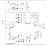
I don't like TI's idea to solder many OPA in line, so I choose another topology - tween-T high Q (1000-2000) filter. Only one dual OPA is required to get fully differential pure sine wave. Tunning is slightly complicated, to get such Q, but filter is easily scaled to any frequency up to 200 kHz.
stm32F7/H7 series can drive both, ADC and internal DAC to generate sine wave. 12-bits is sufficient to get -70dBc THD level, frequency up to MHz area, simple magnitude control using DDS - eradicate any problems usually associated with magnitude stabilisation in common oscillator.
https://www.ti.com/lit/ug/sbau289/sbau289.pdf
I used same concept for testing mcp3561R & max11270 ADC.
https://www.diyaudio.com/community/...ty-from-microchip-mcp3562.374181/#post6709284
I don't like TI's idea to solder many OPA in line, so I choose another topology - tween-T high Q (1000-2000) filter. Only one dual OPA is required to get fully differential pure sine wave. Tunning is slightly complicated, to get such Q, but filter is easily scaled to any frequency up to 200 kHz.
stm32F7/H7 series can drive both, ADC and internal DAC to generate sine wave. 12-bits is sufficient to get -70dBc THD level, frequency up to MHz area, simple magnitude control using DDS - eradicate any problems usually associated with magnitude stabilisation in common oscillator.
Attachments

? I keep options for DAC open, having flexibility to use my Rigol x1000 SG (HD-2 ~72dBc) or as I say stm32f7 internal DAC (about the same ~70dBc), this demands about 60 dB attenuation for HD-2. 10-th order LPF is not something I'd enjoy to build, though tween-T save me of troubles.
Haven't try ES9038 - not hobby friendly package. I get last month ES9023 & PCM1798 to play with. Observed results from es9023 as expected, not really exciting. PCM 1798 much better, HD-3 close to -130 at 1 kHz, same time HD-2 hardly get to -120 , and I think ne5534 is an obstacle. Anyway, nether of them would be able to operate at 100 kHz with acceptable -100 dB, so I will continue to improvise with tween-T. Thinking to build a bunch of them, 8-16 and simply switch a spot frequency by relay, from 100 Hz to 1 MHz
Haven't try ES9038 - not hobby friendly package. I get last month ES9023 & PCM1798 to play with. Observed results from es9023 as expected, not really exciting. PCM 1798 much better, HD-3 close to -130 at 1 kHz, same time HD-2 hardly get to -120 , and I think ne5534 is an obstacle. Anyway, nether of them would be able to operate at 100 kHz with acceptable -100 dB, so I will continue to improvise with tween-T. Thinking to build a bunch of them, 8-16 and simply switch a spot frequency by relay, from 100 Hz to 1 MHz
- Home
- Design & Build
- Equipment & Tools
- Low-distortion Audio-range Oscillator