I read that from here: https://www.audiosciencereview.com/forum/index.php?threads/e1da-cosmos-adc.27038/page-2#post-946458The OPA1656 as follower in non inverted mode has 2H at app. -150dB at 1kHz 2,7VRMS.
It is from the latest schematic from Vic.Very nice , you have the FET to 0V not in serie with the input . Is it the same /same or ...?
In the schematic you posted, the distortions performance will be limited by followers before twin T.
I may be missing something but it looks to me like the inverter has a gain of 2. I think that would unbalance the balanced output.
The OpAmp with the AGC runs gain -1. The filter also has a gain of -1 at the center frequency, the 2C//0.5R + C+R affords that.I may be missing something but it looks to me like the inverter has a gain of 2. I think that would unbalance the balanced output.
See my post here.
Yes, unfortunately. But you sometimes need the follower because the notch only has an input impedance of about 1.8k .. 3.6k.In the schematic you posted, the distortions performance will be limited by followers before twin T.
Bootstrapping its supply to eliminate any CM voltage sure would help. And while we are at it, we could make this composite to have some gain at our audio frequencies of interest as well.
I was referring to the output drive. See the circled areas. Usually you want a gain of -1 for the balanced drive. And why 15K + 1K? In my experiece using a lower resistance lowers the noise and these opamps have no problem driving as low as 600 Ohms.The OpAmp with the AGC runs gain -1. The filter also has a gain of -1 at the center frequency, the 2C//0.5R + C+R affords that.
See my post here.
Attachments
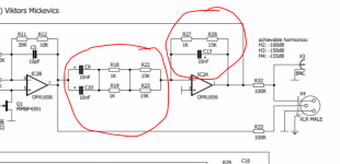
This is not just output drive, please note the feedback. It's the bandpass core of the oscillator and it has a gain of -1 at the oscillation frequency.I was referring to the output drive. See the circled areas. Usually you want a gain of -1 for the balanced drive. And why 15K + 1K? In my experiece using a lower resistance lowers the noise and these opamps have no problem driving as low as 600 Ohms.
15k + 1k is just to get along with E12 values. And that impedance level was choosen to have small capacitor values, 10nF in this case, to get 1kHz. Also, Viktors (the original designer) likely wanted to have no excessive load current to avoid distortion.
For more answers about design decisions maybe better ask Viktors (@vicnic) directly.
This is true. But if the loads are too high, the first harmonics already appear. The OP amp should remain in class A condition.In my experiece using a lower resistance lowers the noise and these opamps have no problem driving as low as 600 Ohms.
I haven't visited this thread in a couple of hundred pages but thought I should check in.
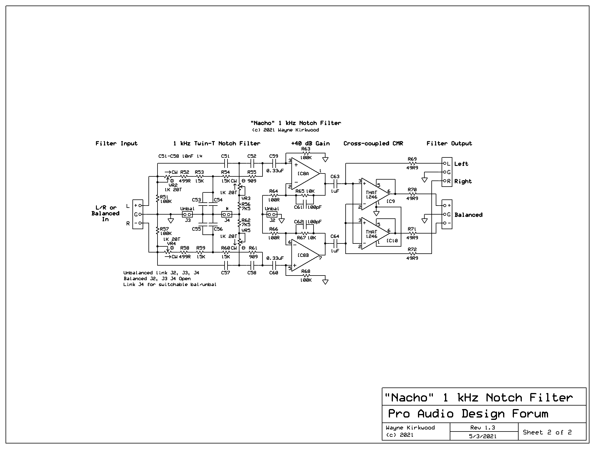
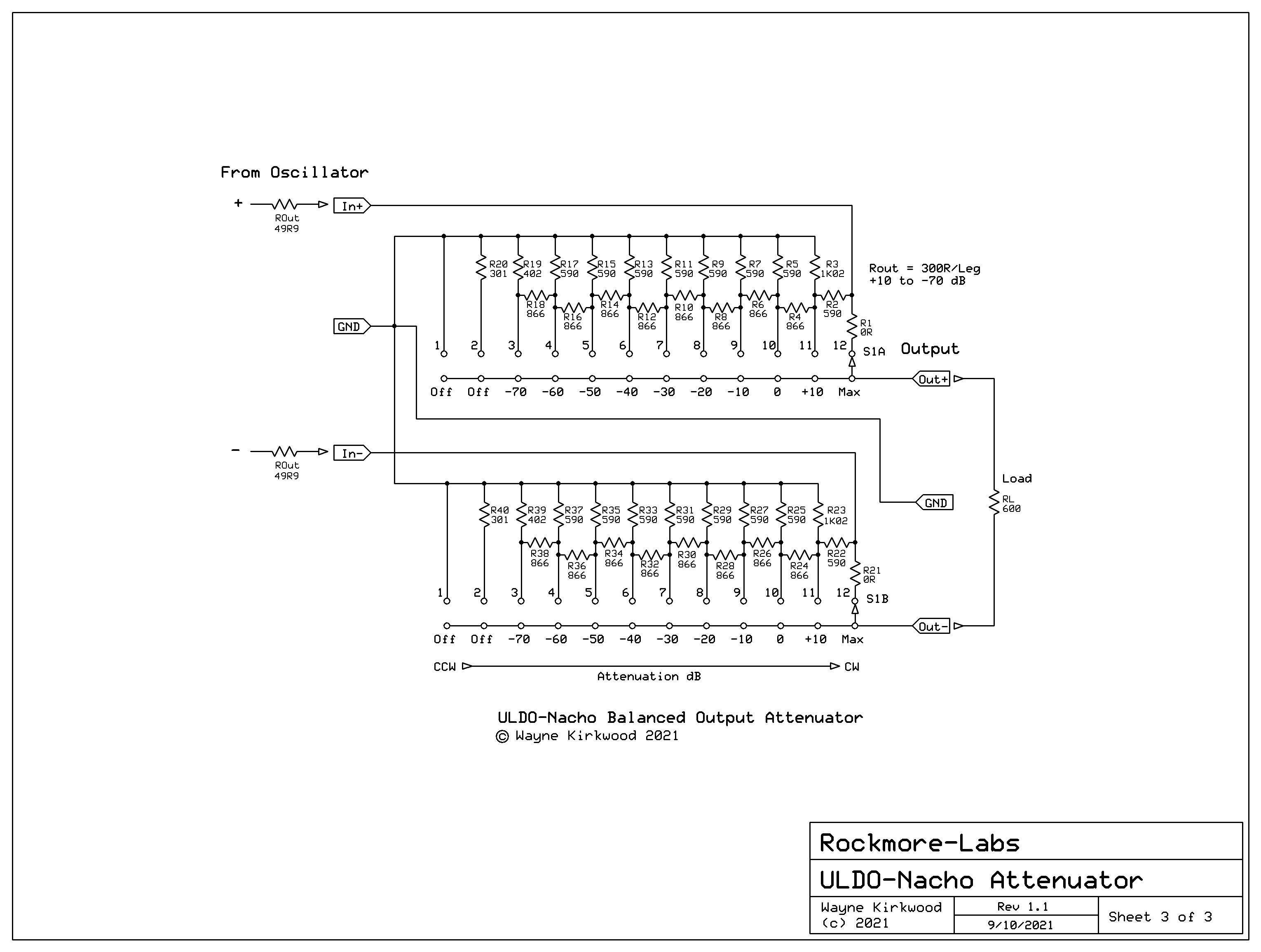
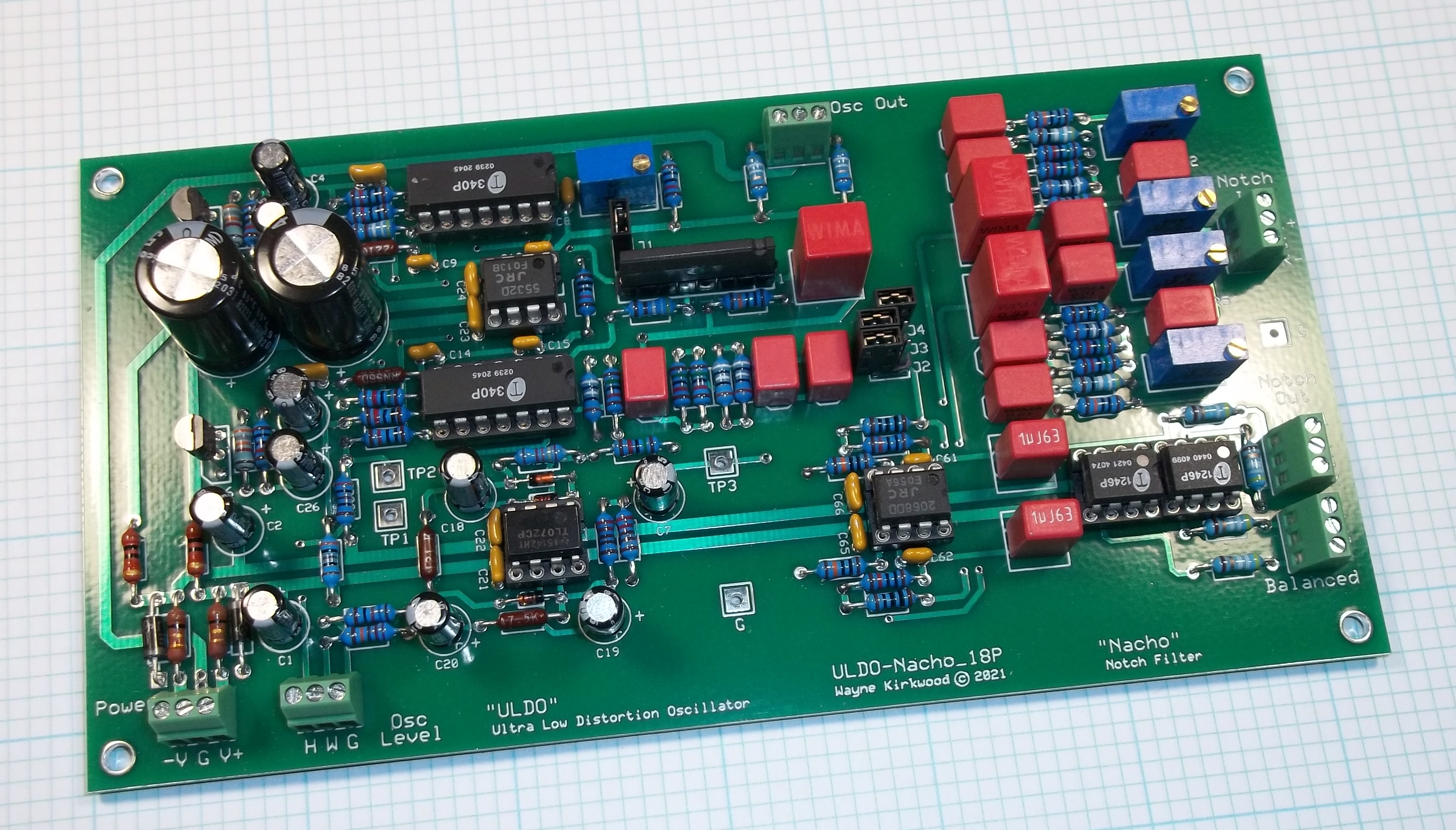
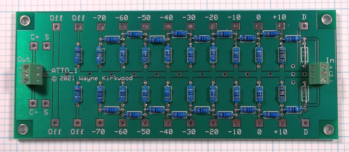
Some time ago I modified Vic's oscillator to use a degenerated VCA and provide a balanced output. I also added a dual channel (or balanced) notch filter to expand A/D measurement range. I later added an attenuator. I call them ULDO-Nacho and Atto. I've found it to be a very worthwhile addition to my bench.
The design uses a "composite" op amp and a common 5532 which outperforms both the OPA1612 and EMI-prone LME49720.
THD runs about -140 dBc depending on level and load.
Enjoy;
Wayne
https://www.proaudiodesignforum.com/forum/php/viewtopic.php?f=7&t=1265
ULDO (Ultra Low Distortion Oscillator)

"Nacho" (Notch Filter)
"Atto" (Attenuator)
Some time ago I modified Vic's oscillator to use a degenerated VCA and provide a balanced output. I also added a dual channel (or balanced) notch filter to expand A/D measurement range. I later added an attenuator. I call them ULDO-Nacho and Atto. I've found it to be a very worthwhile addition to my bench.
The design uses a "composite" op amp and a common 5532 which outperforms both the OPA1612 and EMI-prone LME49720.
THD runs about -140 dBc depending on level and load.
Enjoy;
Wayne
https://www.proaudiodesignforum.com/forum/php/viewtopic.php?f=7&t=1265
ULDO (Ultra Low Distortion Oscillator)
"Nacho" (Notch Filter)
"Atto" (Attenuator)

Crazy. I have never seen such a realization with a VCA. What exactly is the function of the matched BJT on the 5532?
The added differential stage at the 5532 input increases the open loop gain.Crazy. I have never seen such a realization with a VCA. What exactly is the function of the matched BJT on the 5532?
Last edited:
Okay. The OPA has an open loop gain of typ. 154 dB. Wouldn't it be easier to just take this one?The added differential stage at the 5532 input increases the open loop gain.
What part number are you referring to? (OPA what? OPA1612?)
Make sure you compare open loop gain at 1 kHz, the operating frequency, and not DC.
EDIT: Just looked at the aforementioned OPA1656 and its open loop gain at 1 kHz is only 90 dB - about the same as an unassisted 5532.
Make sure you compare open loop gain at 1 kHz, the operating frequency, and not DC.
EDIT: Just looked at the aforementioned OPA1656 and its open loop gain at 1 kHz is only 90 dB - about the same as an unassisted 5532.
Last edited:
Page 8 of the OPA1656 data sheet is where you need to look.
TI doesn't publish open loop gain vs frequency for the 5532 and NJM only lists gain at 10 kHz but they typically run about 90 dB at 1 kHz. Some of the older datasheets (Fairchild) provide gain vs. frequency and its 90 dB. The LME49720 isn't much better.
If you follow the build thread posted earlier there's a theory of operation and also links to a development thread where I looked at other designs from Cordell, Bateman, Williams et al. There are two VCA-based examples.
I estimate, based on crude measurement, the gain with the BJT front-end results in a composite 1 kHz open loop gain in the 135-140 dB range.
I borrowed this trick from a now-defunct Geocities site by the user "Flip Flop World" cxb00463.
I have some concerns, while to presented solutions do not cover fully the DUT situations. As currently, only interests to analyze the Oscillator.
What I am missing for the dream system:
1) a buffered low drive oscillator output (balanced none balanced) to drive a DUT even low input impedance 😀
2) may required using some attenuation for the oscillator, even valid as 1)
3) The DUT output may a power amplifier, so we need some attenuation for the Notch
4) the Notch input may high impedance too, as required to drive the Notch topology
5) Notch topology may with low 2H attenuation as seen on AP gear 😀 and output gain option
6) The Input of the ADC may low impedance, as comes from the Notch output, so we need a Notch output buffer
7) and this all on all parts with low THD and noise 😀
just my 2 cents
Buy QA480 and QA403 ;-)I have some concerns, while to presented solutions do not cover fully the DUT situations. As currently, only interests to analyze the Oscillator.
What I am missing for the dream system:
1) a buffered low drive oscillator output (balanced none balanced) to drive a DUT even low input impedance 😀
2) may required using some attenuation for the oscillator, even valid as 1)
3) The DUT output may a power amplifier, so we need some attenuation for the Notch
4) the Notch input may high impedance too, as required to drive the Notch topology
5) Notch topology may with low 2H attenuation as seen on AP gear 😀 and output gain option
6) The Input of the ADC may low impedance, as comes from the Notch output, so we need a Notch output buffer
7) and this all on all parts with low THD and noise 😀
just my 2 cents
- Home
- Design & Build
- Equipment & Tools
- Low-distortion Audio-range Oscillator