Ralph, looks very nice!
I have one question, how do you related generator dBFS level to distortion in dBc?
Jan
I have one question, how do you related generator dBFS level to distortion in dBc?
Jan
Hi,
I'm considering a Tektronix SG505 purchase. From the very limited info around I can't seem to find a good measurement for this instrument. Has anyone ever bothered measuring its output? A typical distortion figure of 0.0003% seems rather optimistic.
I'm considering a Tektronix SG505 purchase. From the very limited info around I can't seem to find a good measurement for this instrument. Has anyone ever bothered measuring its output? A typical distortion figure of 0.0003% seems rather optimistic.
This is a very good state variable oscillator designed by Bruce Hofer while he was at Tektronix before he helped found Audio Precision. 0.0003% is definitely possible if it is specified at 1 kHz. I have not measured one, but it is possible that it could be in that range at higher frequencies like 10 kHz or 20 kHz if the measurement is THD only, as opposed to THD+N.
Cheers,
Bob
Cheers,
Bob
Hi Bob,
thanks for the info. I went ahead an got myself one unit. When it arrives I will hook it up to my PCM4222 ADC and see what happens.
I'm also considering an upgrade to the opamps just to see what the numbers will show.
thanks for the info. I went ahead an got myself one unit. When it arrives I will hook it up to my PCM4222 ADC and see what happens.
I'm also considering an upgrade to the opamps just to see what the numbers will show.
I still have an old HP, (209 I think) but in reality, use freeware on a PC more. You can generate mathematically perfect and with a $100 DAC, get .0000-something distortion.
Hello all,
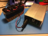
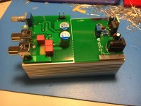
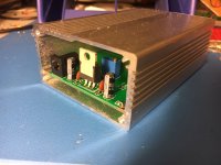
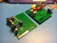
I have made a simple LM317HV-based power supply PCB for vicnic's oscillator.
The board is long enough to leave just a small gap between it and vicnic's board. A small piece of foam or similar can be pinched between the two board ends as the enclosure ends are screwed into place, to take up the gap.
(the case used is the ebay 100*65*35mm extruded aluminum enclosure 1pcs White Electrical Instruments Aluminum Box 100*65*35mm DIY | eBay ).
Caveats:
- turns out I misjudged the needed range of the adjustment pot: the output was high and even after adjusting the pot all the way to one end the output was still at 35.75V.
- the supply by itself does not have enough load to permit regulation. you need to use a resistor (5.6k worked fine for me) to load the output before you can adjust the pot.
- in retrospect, the LM317 is placed a bit close to the rear enclosure panel. make sure you bend it forward a bit to avoid any possibility of the TO-220 tab shorting against the enclosure.
Attachments

Last edited:
Note: simply omitting R2 allows for a wider range of adjustment, which allowed me to dial in exactly 35V.
Hello,
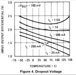
LM317HV isn't really suitable for battery powered operations. It has a significant dropout voltage which leads to a short use time. It is instead necessary to implement a LDO regulator. Those usually have around 200mV dropout voltage. Some examples would go even lower at low currents.
LM317HV isn't really suitable for battery powered operations. It has a significant dropout voltage which leads to a short use time. It is instead necessary to implement a LDO regulator. Those usually have around 200mV dropout voltage. Some examples would go even lower at low currents.
Attachments
Hello,
LM317HV isn't really suitable for battery powered operations. It has a significant dropout voltage which leads to a short use time. It is instead necessary to implement a LDO regulator. Those usually have around 200mV dropout voltage. Some examples would go even lower at low currents.
Practically speaking, it wouldn't make much difference.
We need a 35V output. For an LM317, the 1.5V dropout puts our requirement at 36.5V, so rather than 4 batteries (36V), we instead need 5 (45V).
Our circuit will cease regulation when each 9V reaches a discharge level of 36.5 / 5 = 7.3V. This is quite deep into the discharge curve, which means we extract most of the life out of the battery, which is good.
If we instead used an LDO with 200mV dropout, our circuit would work down to a discharge level of 35.2 / 5 = 7.04V. What additional amount of run-time would 7.04V vs. 7.3V translate into? I'm guessing maybe an additional 5% or 10% at best?
Of course, a 200mV dropout would also allow for operation on 4 batteries, but this would only allow for a discharge depth of 35.2 / 4 = 8.8V, yielding a very short battery life.
So from my perspective, I disagree with language like "isn't really suitable", "short use time" and "It is instead necessary".
But if you still feel that the 317 isn't appropriate, I encourage you to contribute a PCB design with an LDO 😉
Last edited:
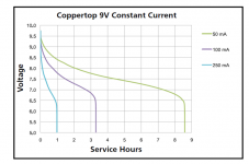
Hmm, actually if the attached discharge curve is correct (and we guess what a 25mA curve would look like), the slope doesn't become drastic until about 6.7V.
So an additional 0.26V of discharge depth might be handy. 🙂
edit: source Design Battery Powered Applications | Dev Center
So an additional 0.26V of discharge depth might be handy. 🙂
edit: source Design Battery Powered Applications | Dev Center
Attachments
Last edited:
Please note that no good design should ever allow for such a small delta V across LM317HV. In practice the regulator might stop doing it's job long before that.
From LM317HV datasheet:
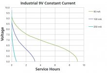
Now lets use a good battery datasheet and do some thinking. From Duracell's ID1604(6LP3146).
Let's get this 50mA load current. Let's be optimistic here and assume that 317HV does in fact really work properly at delta V = 1.5V. So 36.5/5 = 7.3V. Looking at the plots we get around 3 hours useful battery life.
Now let's consider an of the shelf LDO regulator like TI's TPS7A16. At 50mA we get around 150mV Vdrop @ +25 deg.C. So we get 35.15/7 = 7.03V which translates to about 4 hours of useful life or +33% longer operation at 50mA load current.
From LM317HV datasheet:
Unless otherwise specified, these specifications apply:−55°C≤TJ≤+150°C for the LM117HV, and 0°C≤TJ≤+125°C for theLM317HV; VIN−VOUT= 5V and IOUT= 0.1A for the TO-39 package and IOUT= 0.5A for the TO-3 and TO-220 packages.
Now lets use a good battery datasheet and do some thinking. From Duracell's ID1604(6LP3146).
Let's get this 50mA load current. Let's be optimistic here and assume that 317HV does in fact really work properly at delta V = 1.5V. So 36.5/5 = 7.3V. Looking at the plots we get around 3 hours useful battery life.
Now let's consider an of the shelf LDO regulator like TI's TPS7A16. At 50mA we get around 150mV Vdrop @ +25 deg.C. So we get 35.15/7 = 7.03V which translates to about 4 hours of useful life or +33% longer operation at 50mA load current.
Attachments

Vicnic oscillator doesn't need external regulators at all (with voltages slightly higher than 35 V). It has it's own. And 4 batteries give 37-38 V when new. That is absolutely fine for original circuit (all of them with shunt regulators).
It's consumption is about 25 mA. I used wirewound 100-200 R resistor (powerful potentiometer) to drop voltage a bit, but there is not need in it at all.
It's consumption is about 25 mA. I used wirewound 100-200 R resistor (powerful potentiometer) to drop voltage a bit, but there is not need in it at all.
Last edited:
Vicnic oscillator doesn't need external regulators at all (with voltages slightly higher than 35 V). It has it's own. And 4 batteries give 37-38 V when new. That is absolutely fine for original circuit (all of them with shunt regulators).
It's consumption is about 25 mA. I used wirewound 100-200 R resistor (powerful potentiometer) to drop voltage a bit, but there is not need in it at all.
It's an effective way to ruin your power source's output impedance.
Vicnic oscillator doesn't need external regulators at all (with voltages slightly higher than 35 V). It has it's own. And 4 batteries give 37-38 V when new. That is absolutely fine for original circuit (all of them with shunt regulators).
It's consumption is about 25 mA. I used wirewound 100-200 R resistor (powerful potentiometer) to drop voltage a bit, but there is not need in it at all.
The board needs 35V DC +/-0,5V supply. Of course, the current consumption is 25 mA, when the board runs from 35VDC. If the voltage will be higher, the onboard shunt regulators may be overheated.
The powering scheme with shunt regulators and two ballast resistors 100 ohm (each in each wire) was designed for to eliminate parasitic ground loops in different situations, and this doesn't mean that the board can run without an external stabilizer.
With the shunt regulators a current source would be the best solution- supply noise will be reduced the most by the shunt action. It would also provide the longest battery life being a constant current of 26-30 mA. Enough to get the regulators into operation and supply the rest of the circuit. I have been using this with LM317's as a current source for 5 years and it works fine. 9V batteries have around 4 hours life (I have not measured it) and the complete isolation from external power sources has been essential for determining internal power related noise in DUT's. If using a common supply for more than one active oscillator there are a handful of considerations to keep the output of one from interacting with the others. I use separate batteries for each in my array of 3 oscillators so zero interaction.
I second the constant current source solution. Very predictable. Nothing gets hot. It seems to work great for me.
I use Nanophosphate batteries that I have around for other purposes. I can't tell you how long those last, since I've never operated the oscillators long enough at one sitting to find out! A couple days before a recharge is needed, I'd guess. With larger battery packs (more cells in parallel) you could go a week of continuous operation between charges.
I use Nanophosphate batteries that I have around for other purposes. I can't tell you how long those last, since I've never operated the oscillators long enough at one sitting to find out! A couple days before a recharge is needed, I'd guess. With larger battery packs (more cells in parallel) you could go a week of continuous operation between charges.
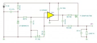
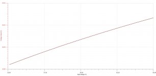
Here's a quick "discrete" LDO design. It's based on a high-voltage opamp - TI's OPA551. The series pass element is a P-channel MOSFET. The voltage reference is a simple zener diode operating at around 500uA.
The graph shows the output simulation for Vin = 35.1 to 45V.
The graph shows the output simulation for Vin = 35.1 to 45V.
Attachments
- Home
- Design & Build
- Equipment & Tools
- Low-distortion Audio-range Oscillator