Yep, it turns out to buy some SS, I have many projects where I can replace batteries, including an old nice Radford ANM2.
Whether you use a bunch of 9 VDC dry cells and a current regulator or Jan's more elegant solution, the big thing is the isolation from the AC mains. The SilentSwitcher has the distinct advantage of being able to use commonly available 5 VDC battery supplies you might have around the house to keep your phone charged. If you don't have such a supply, they're pretty cheap and you almost definitely already have a suitable charger for it.
Speaking of mains isolation, has anybody tried to make a poor man's line isolation transformer using the 2 primaries of a 120-V/240-V power transformer? If I had to guess, I might think that a 500 VA power transformer could do 250 VA in such a use.
Obviously, the degree of isolation would be limited by the inter-winding capacitance between the 2 primaries.
Cheers,
Bob
Yes.
Yes.
And, as you guessed. Two 120 VAC to 12 VAC transformers back-to-back worked and measured better. Different filtering possibilities between the 12 VAC windings, too.
The 12V 7Ah VRLA type battery monoblocks are ubiquitous (as they are used in small to moderate size UPS) and can be charged from modern cheap vehicle smps chargers, and make an excellent battery supply for instrumentation (I use them for USB soundcard powering, and USB isolators, and class D interface amps and some DC powered vintage oscillators etc). A cheap (ebay) boost converter pcb assembly will get 12V up to a regulated 35Vdc, and the switching frequency is typically above measurement system range. The battery and converter can sit in a loosely fitting metal enclosure, as there is effectively no power dissipation. It's always nice to remove any mains powered supply that could add parasitic noise loop to other measurement/DUT equipment.
Last edited:
The 12V 7Ah VRLA type battery monoblocks are ubiquitous (as they are used in small to moderate size UPS) and can be charged from modern cheap vehicle smps chargers, and make an excellent battery supply for instrumentation (I use them for USB soundcard powering, and USB isolators, and class D interface amps and some DC powered vintage oscillators etc). A cheap (ebay) boost converter pcb assembly will get 12V up to a regulated 35Vdc, and the switching frequency is typically above measurement system range. The battery and converter can sit in a loosely fitting metal enclosure, as there is effectively no power dissipation. It's always nice to remove any mains powered supply that could add parasitic noise loop to other measurement/DUT equipment.
Another nice thing about battery-powered circuits is that you can throw them into a faraday cage for low-noise measurements 🙂
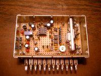
an evening with the ICL7660 - Page 1
These days I use 18V NiMH drill batteries.
Attachments
Many measurement instruments like HP, Radford and Brüel & Kjaer had the option of battery operation, I own some such old goodies, oscilloscopes and measuring amplifiers, rechargeable lead batteries can also work and can be charged with simple cheap chargers, but guess that you still have to have a good regulator, Jan Didden SS or some cheaper regulator.
I'm using an Asus Xonar Essence STX card as an ADC (I also have an Altor Olivine2).
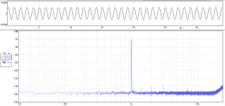
With the following path- WaveGene ---> USB/SPDIF ---> DAC ---> buffer box --> Asus - I am seeing about 0.00018% THD.
Would I really benefit from building a low THD oscillator?
Are my THD figures just being reported incorrectly by WaveSpectra perhaps?
With the following path- WaveGene ---> USB/SPDIF ---> DAC ---> buffer box --> Asus - I am seeing about 0.00018% THD.
Would I really benefit from building a low THD oscillator?
Are my THD figures just being reported incorrectly by WaveSpectra perhaps?
Attachments
For me it is good to have a known reference for calibration, this Victor Oscillator is well known and cheap, it will be a kind of THD standard device.
I would like to bring my THD calculator to your attention right away.
How should this be used?
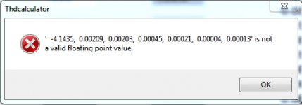
I have run a plot in Arta Steps - exported it to CSV and then imported it in your THD Calculator.
I get some errors on import but the program then goes on to calculate a seemingly improbably low THD figure of 0.000006% ?
I suspect I am doing something wrong...
Attachments
How should this be used?
I have run a plot in Arta Steps - exported it to CSV and then imported it in your THD Calculator.
I get some errors on import but the program then goes on to calculate a seemingly improbably low THD figure of 0.000006% ?
I suspect I am doing something wrong...
I haven't invested a lot of time in error handling of the ARTA import. If you take the export from the latest ARTA version and don't change it, then it should work. I don't use Steps.
I just ran across this: download - KO4BB. Its an interesting approack that pulls multiple phase from a single oscillator, using only a few tube!. Implementing with opamps should be pretty straightforward.
Also interesting are the inventors. Frank McIntosh of McIntosh fame and Peter Sulzer who was responsible for once of the first real low phase noise crystal oscillators http://leapsecond.com/museum/sul25-1/ I never would have connect them even though they were contemporaries.
Also interesting are the inventors. Frank McIntosh of McIntosh fame and Peter Sulzer who was responsible for once of the first real low phase noise crystal oscillators http://leapsecond.com/museum/sul25-1/ I never would have connect them even though they were contemporaries.
I just ran across this: download - KO4BB. Its an interesting approack that pulls multiple phase from a single oscillator, using only a few tube!. Implementing with opamps should be pretty straightforward.
Also interesting are the inventors. Frank McIntosh of McIntosh fame and Peter Sulzer who was responsible for once of the first real low phase noise crystal oscillators http://leapsecond.com/museum/sul25-1/ I never would have connect them even though they were contemporaries.
This is cool. Its amazing what they could do back then with the crude technology they had to work with, including virtually no computer simulation capability.
Today, it is easy to get multiple phases out of a state variable oscillator. Getting in-phase and quadrature is easy and natural. I've used it to build low-ripple rectifiers for oscillator agc. Having 4 phases makes a huge difference. I have also simulated generating 8 phases by adding together each adjacent pair of the four phases.
Cheers,
Bob
Well, I was there and frankly I'm just appalled by these old nasty big hacks. OK, I made a couple myself. They were unstable and inaccurate. God bless the inventor of DDS.
Don't forget that when measuring distortion with ARTA using an external oscillator source, you need to set the 'Generator' frequency setting in ARTA to be exactly that of the external oscillator for the ARTA measurements to be accurate.
A few Hz off will give erroneous readings.
Cheers
Mike
A few Hz off will give erroneous readings.
Cheers
Mike
Last edited:
Only if you care about the computed THD percentage. If you're doing A/B testing to see if you made an improvement, you can just use the amplitude of the harmonics. I usually set the reference level of the FFT display to put the fundamental peak at 0 dB. That makes it pretty straight-forward to read the THD level in dB.
Tom
Tom
Don't forget that when measuring distortion with ARTA using an external oscillator source, you need to set the 'Generator' frequency setting in ARTA to be exactly that of the external oscillator for the ARTA measurements to be accurate.
A few Hz off will give erroneous readings.
Cheers
Mike
Can't you set ARTA to threat the highest signal as the fundamental? Most such programs can do that.
Jan
Only if you care about the computed THD percentage. If you're doing A/B testing to see if you made an improvement, you can just use the amplitude of the harmonics. I usually set the reference level of the FFT display to put the fundamental peak at 0 dB. That makes it pretty straight-forward to read the THD level in dB.
Tom
Yes OK, OK I forgot to state 'measuring distortion percentage' which is what most people would be looking for.
Measuring individual harmonics' levels and then calculating them long hand is a PITA beyond the third harmonic and gets worse if you use a passive notch filter and take account of its attenuation effects on the 2nd and 3rd harmonics. I was trying to point out to previous posters that there is a little 'gotcha' there in my experience.
Hi Jan
my understanding is that ARTA does not present the fundamental's frequency value unless you align the cursor exactly on the peak. It does, however, display the RMS value of the input signal.
For distortion percentage measurements, it assumes that the soundcard in use generates the test signal. I would be interested if Ivo could confirm that or not.
Regards
Mike
Last edited:
- Home
- Design & Build
- Equipment & Tools
- Low-distortion Audio-range Oscillator