An oscilloscope is ideal, and 40MHz should be enough. An amplifier won't generally oscillate close to its unity gain frequency, because it's running out of gain to support an oscillation up there. So, a 40MHz scope should be fine to work with a 55MHz amplifier. Note - the 55MHz quoted for the gain bandwidth product of the OPA1656 is not the same as the unity gain frequency. The unity gain frequency as seen on the datasheet gain-phase plot is only 20MHz, but the amp has more gain bandwidth at lower frequencies. So, a 40MHz scope will be fine.
You need to use a 10x probe to prevent the probe capacitance from altering the circuit too much. Sometimes, the capacitance of the probe can stabilize the amplifier, and make you think it is not oscillating. Or, vice versa - it can de-stabilize an amplifier and cause it to start oscillating when it was not before. But, circuits that are this finicky should probably be considered "broken" anyway. If you place your hand close to the circuit and things change, you know it's marginally stable anyway.
When measuring high frequencies like this, you need to choose your probe ground point carefully - it should be close to the point that you're measuring. It's also a good idea to touch the probe to ground and look at the random RF garbage that you see and take that as a baseline reading, then compare that to the amplifier output. If the two look the same, and everything is less than a dozen or two millivolts, then it's probably not oscillating. AM radio broadcast will creep into everything so the trace will not be flat at all. That's why you want to compare the probed ground to the probed amplifier output and look to see what's different.
The 'high end' way to do this is to use a differential probe, but a high speed differential probe is pretty expensive, and they're easy to blow up, making it iffy to buy one used. A cheap alternative if you have a dual trace scope is to use two matched probes and get the vertical amplifier to invert one probe and sum the two probes together. You now have an el cheapo differential probe that will show you the voltage between two nodes, so you don't have to pretend that ground is the same everywhere - a bad assumption above 1MHz. You can trim out the common mode rejection by placing one of the probes in variable gain mode and adjusting the gain of one to trim out all output when the two probes are both connected to the same signal.
The add-invert differential probe trick is easy to do on an older Tektronix analog scope, and I can almost convince my Rigol to do that, but I bet it's easier than I imagine if I knew how to use the Rigol better. Your analog scope will probably be ideal for this use.
Thanks, this is really helpful.
I was reading an oscilloscope manual for the first time in my life last night. (A beginner like me can't make sense of a scope manual unless you have the scope in front of you.) So I can now say I understand at least some chunks of what you're saying. And yes, my scope has an invert button and I can sum the two probe inputs, so invert+sum will give me difference. Will definitely try it.
Mine is an analog + digital scope, which can operate in either of these modes. The Metrix OX8050. Probably 10 years old when it came to me last week. I'm keeping the digital functionality aside for later.
What's a 10X probe? My probes are switchable 1X/10X. Aren't they all? Did you mean use the probe in the 10X setting? And does one need to calibrate each probe separately for 1X and 10X?
Last edited:
Some budget probes are switchable between 1x and 10x, but many of the higher end probes are either 1x or 10x, with 10x more common. The reason for 10x is that the attenuator built into the probe is able to isolate the probe cable's capacitance, and minimize the capacitance at the probe tip, and this makes the probe able to influence the circuit a lot less than a simple 1x probe, which is basically a fancy piece of coax. The absolute minimum capacitance requires an active probe with a FET amplifier at the probe tip, but again, those are very expensive and easily destroyed with excess voltage, so they are hard to find as a bargain used.
I'd tape up the 1x / 10x switch so it stays in 10x mode and calibrate the probe for that. I find the Rigol probes to be really fiddly and that switch gets changed by accident too often - I need the probe to be only 10x, so I taped mine up.
Glad you have the add-invert functions! That should make your life a lot easier.
OK, I believe I'm drifting the thread here a bit much, so if it's annoying, could a moderator move us to another thread? 🙂
One thing to be aware of in high speed opamps is the capacitance hanging off the inv input. The package may have already 2pF and DIL socket can easily add another 3 or 4pF. Then, if you use a ground plane, the trace to the inv input can add a lot more. All that capacitance adds phase shift in the loop and if you don't take counter-measures - presto! you build yourself an oscillator!
That is one reason why a high-speed opamp may not be a drop in replacement for a low-bandwidth opamp.
Jan
That is one reason why a high-speed opamp may not be a drop in replacement for a low-bandwidth opamp.
Jan
NE5532 is the poor man's op amp. With a capacitor of 0..100pF you can set any bandwidth you want. Brilliant!
IF you have a probe that can be switched between x1 and x10, you should use epoxy and glue it permanently in the x10 position. With new scopes especially, if that switch goes to the x1 position while you are connected to a high signal voltage, you can damage the input amplifier of that scope (read: Expensive!). If you need to view a signal in the x1 setting, use BNC cables. That way you will be certain as to whether you are using a x1 or x10 cable. All the expensive passive cables are x10 or x100 types.
-Chris
-Chris
A very simple way to test for oscillations, if you don't have a scope, is using what hams call a detector probe.
It consists of a small-signal diode like the 1N4148 and a small capacitor, like 100pF. The capacitor is connected with one end to the point you want to test, like an opamp output. The other end of the cap goes to the K of the diode, the A of the diode goes to ground. Measure with a DC ultimeter across the diode for DC. If there is DC, the circuit oscillates.
Jan
Beautiful! 😀A very simple way to test for oscillations, if you don't have a scope, is using what hams call a detector probe.
Won't the act of holding this gizmo in my hand and touching it to the circuit toggle the oscillation in some cases?
Good point yes it could if there is no outbuild series R. Play it safe use 100R in series with the cap. Also for max sensitivity try to find a vintage Ge diode.
Jan
Jan
This is exactly what my friend (a grizzled analog veteran of a few decades) suggested too.Good point yes it could if there is no outbuild series R. Play it safe use 100R in series with the cap. Also for max sensitivity try to find a vintage Ge diode.
A very simple way to test for oscillations, if you don't have a scope, is using what hams call a detector probe.
It consists of a small-signal diode like the 1N4148 and a small capacitor, like 100pF. The capacitor is connected with one end to the point you want to test, like an opamp output. The other end of the cap goes to the K of the diode, the A of the diode goes to ground. Measure with a DC ultimeter across the diode for DC. If there is DC, the circuit oscillates.
Jan
And will only work if the level is above the diode forward voltage...
I had this issue using an AD797 beast and did swing a bit at 9MHz 😀
Yes of course, that's true, hence the attempt to find a germanium diode, etc...And will only work if the level is above the diode forward voltage...
Check TI SM74611 'Smart Bypass Diode' which lists an average forward voltage of 26 mV at 8 A (no info given below 2 A though...).
Big gotcha: the x10 setting of a regular probe won't help with too high DC applied with the scope set to AC coupling. Regular probes only have a series resistor, the bottom leg of the divider is the 1Meg resistor in the scope which is after the cap. This is true with any regular voltage probe. therefore even the x100 types only have a 300V rating.IF you have a probe that can be switched between x1 and x10, you should use epoxy and glue it permanently in the x10 position. With new scopes especially, if that switch goes to the x1 position while you are connected to a high signal voltage, you can damage the input amplifier of that scope (read: Expensive!). If you need to view a signal in the x1 setting, use BNC cables. That way you will be certain as to whether you are using a x1 or x10 cable. All the expensive passive cables are x10 or x100 types.
-Chris
True HV probes have a 1Meg shunt resistor in the probe so the DC is divided down as well but still there is double the DC voltage vs. AC.
They used to call the RF probe diodes "Hot Carrier Diodes." Today they just call them RF Schotky diodes.
To get astounding sensitivity to RF you use two, both are lightly biased on with a very low current. You couple one of the diodes to the input under test through a small 100 pF ish coupling capacitor. Measuring the DC level difference between them will show signal level.
I use this circuit built into a small case with a battery to align satellite antennas.
Hi KSTR,
Your point is well taken. I just tested two scopes, an Agilent 54642D and a Tek 2465B CT and you are right, the 1 Meg load resistor is only connected when in DC coupling mode. I wonder why they don't leave it in circuit all the time? It is 1 Megohm after all. All you can hope for is that the AC coupling capacitor is a high voltage type, 1 KV would be nice.
-Chris
This also seems handy for detecting oscillations:
RF Active Probe 0.1 - 500 MHz with AD8307 detector | eBay
In the old times (yeah, I know) we all used to have something like this on our bench:
Vtg B&K Precision PR-23 RF Detector Probe w/ Instruction Sheet TV Radio Testing | eBay
Jan
RF Active Probe 0.1 - 500 MHz with AD8307 detector | eBay
In the old times (yeah, I know) we all used to have something like this on our bench:
Vtg B&K Precision PR-23 RF Detector Probe w/ Instruction Sheet TV Radio Testing | eBay
Jan
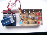
A new problem: The last battery does not fit into the case. I need a bigger case!
Can you turn the batteries the other way?
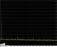
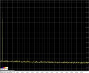
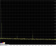
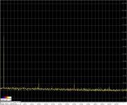
The 10kHz oscillator distortions tests at maximum output (2,7V RMS). Different opamps in the Wien bridge.
Measurements via the passive twin T. Needs to add +4dB at the second harmonic.
1) LME49720
2) OPA1656
3) LME49720 + 1,1kohm load at opamp output
4) OPA1656 + same load
Measurements via the passive twin T. Needs to add +4dB at the second harmonic.
1) LME49720
2) OPA1656
3) LME49720 + 1,1kohm load at opamp output
4) OPA1656 + same load
Attachments
- Home
- Design & Build
- Equipment & Tools
- Low-distortion Audio-range Oscillator