No way. The NE is almost always stable. The LM has 55 MHz bandwidth and likes to oscillate in NE circuits.Will this new opamp drive low impedances as easily as the 5534? Doug Self famously uses these low resistances everywhere to keep noise down; can this opamp be a drop-in replacement in his circuits?
So are the bypass requirements different for this one compared to the NE5534?No way. The NE is almost always stable. The LM has 55 MHz bandwidth and likes to oscillate in NE circuits.
The relationship between the distortion and the settling time has been recently treated theoretically and experimentally in: The dynamics of a stabilised Wien bridge oscillator - IOPscience
It appears that an oscillator with the C7 lamp (120V/40mA) would have the 3rd harmonic approx. 20dB below the one obtainable with the 327 lamp, at a cost of a significantly longer settling time (as already mentioned in the thread).
Regards,
Braca
It appears that an oscillator with the C7 lamp (120V/40mA) would have the 3rd harmonic approx. 20dB below the one obtainable with the 327 lamp, at a cost of a significantly longer settling time (as already mentioned in the thread).
Regards,
Braca
Will this new opamp drive low impedances as easily as the 5534? Doug Self famously uses these low resistances everywhere to keep noise down; can this opamp be a drop-in replacement in his circuits?
The datasheet says that it will produce 100mA output current, which is enormous, much higher than any other low distortion amplifier that I know of, and several times what a 553x can do.
As for a drop in replacement, realize that it is a dual, so it will not replace a 5534, only a 5532. The days of single op amps are numbered. As long as an amplifier's bias current is not pushing the edge of the thermal capabilities of a package, cost considerations favor placing two amps in a single package. Recently, New Japan Radio discontinued the 5534, and TI dropped the LME49710 a year or so ago. So, new amps will be available in singles only if they run really hot, not an issue with the OPA1656.
I haven't access to this paper. Is something said about optocoppler(LED+photocell)?The relationship between the distortion and the settling time has been recently treated theoretically and experimentally in: The dynamics of a stabilised Wien bridge oscillator - IOPscience
It appears that an oscillator with the C7 lamp (120V/40mA) would have the 3rd harmonic approx. 20dB below the one obtainable with the 327 lamp, at a cost of a significantly longer settling time (as already mentioned in the thread).
Regards,
Braca
It may work, but it does not have to. The LM (or any modern op amp) is totally unpredictable because of the high bandwidth.So, you feel this can be a drop-in replacement for the NE5532? No stability concerns etc?
Yes, but there must be a prescribed way to make them stable? I'm asking what changes need to be made to a typical NE5532 based circuit to make it work stably with the new chip? Is this a deterministic problem?It may work, but it does not have to. The LM (or any modern op amp) is totally unpredictable because of the high bandwidth.
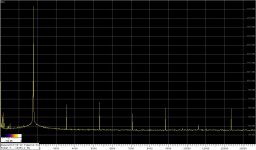
Distortions test @20kHz in the same schematic:
1) LME49720
2) OPA1656
Thanks for the test. It seems that distorton is reduced in this situation. Nevertheless comparing LM and OPA in LTSpice gives +2.6 dB more noise for OPA in notch filter circuit.
Yes, the paper is unfortunately not publicly available. In this country one must merely be a member in a library system to become it free of charge.I haven't access to this paper. Is something said about optocoppler(LED+photocell)?
The AGC methods considered in the paper are the lamp, diodes, and FET.
The best THD I achieved with a 327 lamp and LM4562 is slightly below -100dB, and agrees with the theory presented in the paper (s. attachment).
Regards,
Braca
Attachments
This one?This was all covered by B. Oliver in an HP tech note.
https://www.hpl.hp.com/hpjournal/pdfs/IssuePDFs/1960-04.pdf
No the mentioned paper is
""The dynamics of a stabilised Wien bridge oscillator" L Lerner
Published 13 October 2016 • © 2016 IOP Publishing Ltd
https://iopscience.iop.org/article/10.1088/0143-0807/37/6/065807/pdf
Simple register as guest, but still no given access... may someone helps out

The relationship between the distortion and the settling time has been recently treated theoretically and experimentally in:
The dynamics of a stabilised Wien bridge oscillator - IOPscience
The "first time" comment is interesting, I had this problem using Volterra analysis in a 1966 text book on instrument design.
No the mentioned paper is
""The dynamics of a stabilised Wien bridge oscillator" L Lerner
Published 13 October 2016 • © 2016 IOP Publishing Ltd
You can do this in SPICE with an ideal poly source with a small third order term and the Wein network. Just run a transient analysis (you might need a kick to start it). The oscillators amplitude will stabilize in a time based on the amount of distortion.
BTW Bernard Oliver gave a complete analysis of the lamp oscillator in the HP Journal which is very enlightening. The C7 lamp has a lower voltage coefficient of resistance as opposed to the thermal one, Oliver's paper IIRC explains the interaction of the two effects. This is also why the distortion increases at low frequency.
EDIT @arb Yes, thanks (the maths are difficult)
Index file of past issues of HP Journal
Issues downloadable at: HP Journal - online issues
Issues downloadable at: HP Journal - online issues
Attachments
So, you feel this can be a drop-in replacement for the NE5532? No stability concerns etc?
Probably not a drop-in replacement as they are two very different opamps. In any layout you must cater to the specific part you use. But if you know what to do, any opamp can be made stable in any application. There's nothing unpredictable about it.
Modern opamp data sheets (remember data sheets ? ;-) normally have a section that gives hints and tips for layout and stability considerations, which are basically sure-fire.
Jan
Yes, I'll need to look up the datasheet and any app notes, but before that, I was wondering if any of you have already figured out the differences in the bypassing and/or other stability measures. 🙂
They are both unity gain stable, so there shouldn't be any huge issues with replacing them. I think you would be safe to try one. I have been able to drop in an LM4562 in an NE5532 socket many times in the past with no issues, and I do look for oscillation.
-Chris
-Chris
I just finished reading the application notes portion of the datasheet, and it seems to mention a lot of recommended measures in PCB design to prevent oscillation. I guess if the PCB has been designed with these precautions, it'll work with 5532 or this new chip. But more carelessly designed PCBs may work more easily with the 5532. Is this a reasonable assumption?
Chris, I share your experience, but also found the ne5532 is hard to beat on performance, even by opamps that are theoretically much better.
So, you feel this can be a drop-in replacement for the NE5532? No stability concerns etc?
The OPA1656 is unity gain stable, and I didn't misbehave in my test circuit, but then again, it's a pretty good layout. I'm sure there are pathological layouts that are stable for no reason with the slightly slower NE5532 that will have problems with the OPA1656. However, adding a 20-50pF 1608 SMD package feedback capacitor across the output and inverting input pads should fix even a poor layout up.
The days of really poor layouts that were stable only with slow amplifiers like the RC4558 are gone. When the 5534 came out, designers had to provide at least a somewhat low impedance supply and a somewhat wideband feedback network just to get the 5534 to work, and barring a finicky, marginally stable amplifier, any competent layout from the mid '70s on should work with a well designed unity gain stable amplifier like the OPA1656.
As an anecdote, I recently tried the NJM2068 in the same PCB that works well for the LM4562 and the OPA1656. When I started to measure it, the distortion was really high, around -80dBc, and it puzzled me - it's not supposed to be this bad of an amp. It finally dawned on me to check for oscillation, and indeed, it was oscillating at 1.8MHz in a low gain circuit with 33pF feedback caps and super low impedance supples on a 4 layer PCB. The NJM2068 is apparently not quite unity gain stable, and/or gets really cranky with only a slight amount of output load capacitance (less than 5-10pF in this layout, with the actual cable and connector capacitance isolated by 50Ω).
Doing simulations of the circuit, it also showed instability even with no output capacitive load. I was able to get it to be stable with relatively huge 100pF feedback caps instead of the 33pF I use just for good measure with other amps. Putting those into the PCB removed the oscillation, and distortion dropped to -126 dBc or thereabouts - good, but still about 20dB higher of a measurement than the LM4562 or OPA1656 in the same circuit board.
The point is that it's worth simulating the circuit to make sure that it has some hope of working in the ideal case, and making sure that the PCB layout isn't too far from the ideal case either. Randomly swapping amps into a random circuit board brings no promises at all, so in that case, you have to be prepared to examine the board with an oscilloscope to see if it is oscillating, see if the distortion is high for no reason, or see if the power supply consumption is higher than what the datasheet suggests - these are all signs that the op amp is working overtime doing something other than amplifying your signal. If that happens, you can always add small SMD feedback caps directly across the output and -input pins, and consider whether the power supply bypasses are sufficiently wideband - perhaps swap through hole bypass caps for SMD caps located closer to the amplifiers.
It may work, but it does not have to. The LM (or any modern op amp) is totally unpredictable because of the high bandwidth.
I wouldn't use the word unpredictable. If I use LTspice to simulate the circuit and find that it actually converges and does not oscillate in a .tran analysis, I have had 100% success translating that circuit to a PCB and having that circuit also be stable.
Just as a random example, I have some PCBs next to me that use the LM4562 with a THS4012 amplifier in its feedback loop as a buffer stage, and nothing untoward was needed to be done to get it to be stable in a +2 noise gain circuit. I have another amplifier with the THS3001 in the LM4562 feedback loop, a 420MHz CFB amp, and that too worked well. The only precaution there was to exclude some copper directly underneath the inverting feedback terminal of the THS3001 to prevent it from becoming unstable. The PCB was 4 layer and the inner layer was close to the layer where the THS3001 was placed, making it useful to mask away some of the foil directly below the -input pin. Simulating that capacitance showed that the circuit was stable with more than what I expected from the PCB geometry itself. And, it worked. A ridiculously expensive overkill composite amplifier, but it worked just fine.
All I'm saying is that it is predictable, you just have to use more than luck to design the circuit and layout.
Guys, all this is very insightful and interesting for someone like me. I'm loving it!
How do you know, I mean really know, that a chip is oscillating? By seeing the oscillations on a scope, or is there any other way? If it's on a scope, what kind of scope do you use? I have a 40 MHz analog scope -- new toy, bought used. Will this be adequate for most scenarios?
How do you know, I mean really know, that a chip is oscillating? By seeing the oscillations on a scope, or is there any other way? If it's on a scope, what kind of scope do you use? I have a 40 MHz analog scope -- new toy, bought used. Will this be adequate for most scenarios?
- Home
- Design & Build
- Equipment & Tools
- Low-distortion Audio-range Oscillator