With non-polar caps, especially miniature multi-layer C0G capacitors, adding extra DC bias can add even order nonlinearities, by making the peak field strength across the dielectric higher for one polarity of signal peak vs. the other polarity. This is only an issue with multilayer ceramics, where the dielectric is already exposed to extremely high field strengths, since the dielectric layers are so thin. The theory is that the dielectric starts to saturate at extremely high field strengths, and biasing the cap away from a net zero field strength makes the peak levels worse and also asymmetric relative to the AC signal across the cap.
A nice side effect of this behavior is that one can use this to determine the linearity of an MLCC dielectric in a distortion test by changing only the field strength across the dielectric, without changing the generator level and analyzer levels (which would alter the analyzer fundamental). If you see a change in 2nd harmonic while changing only the DC bias, you have found a nonlinearity caused by dielectric saturation. Presumably, if the same amount of 'squish' happens at a higher DC bias level for one cap compared to another, that's a cleaner cap.
🙂 😎
-RNM
Last edited:
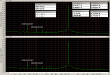
Thank you for this data, I really appreciate it. I was looking at FKP as signal capacitors and might be better than C0G.I found my old tests for 10nF capacitors at 1kHz 2,7V RMS.
Typical figures:
1. COG 1206 200V, 2. COG 1206 630V, 3. Wima FKP2 100V
Do you know / remember the TCR (ppm(C) value of does C0G you tested ???
The data sheets of the measured COG capacitors:Do you know / remember the TCR (ppm(C) value of does C0G you tested ???
https://www.farnell.com/datasheets/...8597.89552060.1553269506-452830816.1512842515
http://www.wlxmall.com/images/item_pdf_new/20180416/TDK184161959/C1608C0G2A821J080AA-cn.pdf
If you look at the datasheet for the Kemet caps its adamant that you keep the voltage constant during testing. Is that because some parameter changes on caps that are supposed to be stable with voltage? I guess I'll need to set up an SMT test fixture soon.
This circuit looks great. I have a Radiometer distortion analyser.For your inspiration
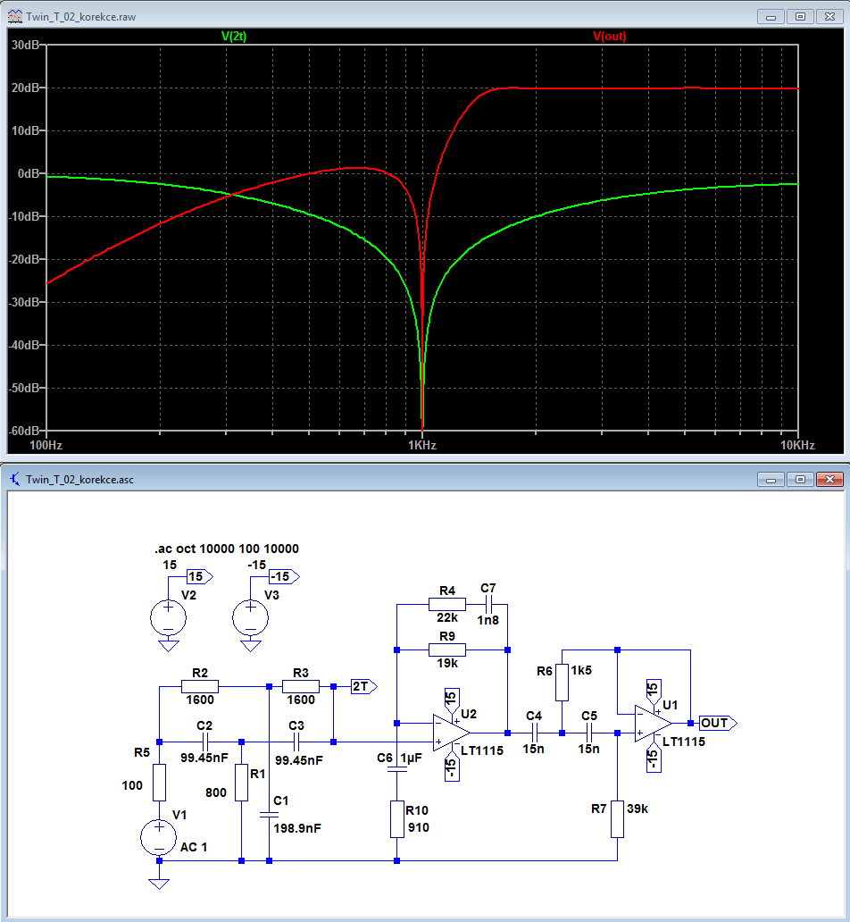
There the notch filter is variable (there is a balance knob to tune the notch) and this needs to be aligned a few times before it stabilises.
Question: can your filter be 'tuned' a bit to be able to match small drifts in frequency? Which resistors should be changed or is that not do-able, 1600/1600/800 cannot be changed in high enough matched quality)?
I am looking to buy this generator:
Sine wave signal generator 1KHz ultra low distortion | eBay
+ and need a corresponding high quality (and high Q) notch filter with low noise.
albert
For your inspiration
Do you have also plotted, on real or simulated circuit, the idle noise floor?
While on ordinary active T-Win Notch, the noise floor rises as a bell around the notch frequency... 😀
Hp
Victor 1KHz generator
After more months of waiting (job related issues) i have finally test Victors 1KHz generator.
Here are the results.
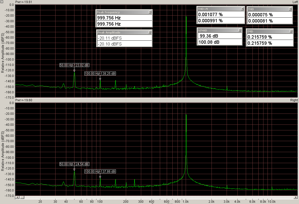
At -10dBFS (here i have some doubts that distortions come from generator)
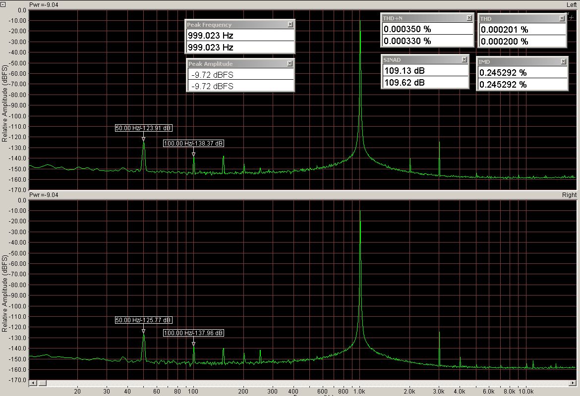
Here is at -10dBFS
I need to work little more at shielding. Thank you Victors!
After more months of waiting (job related issues) i have finally test Victors 1KHz generator.
Here are the results.
At -10dBFS (here i have some doubts that distortions come from generator)
Here is at -10dBFS
I need to work little more at shielding. Thank you Victors!
Attachments
@vicnic: is there a drill template for the position of the holes for the RCA outputs, the LED, the mounting screw and the pot?
Someone probably made one sometime, anybody know?
Jan
Someone probably made one sometime, anybody know?
Jan
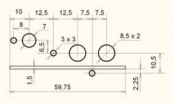
Your in luck Jan. I found it in a folder on my desktop.
Excellent David, thanks!
I´m mounting both a 1kHz and a 5kHz in a common enclosure. These will be the high performance sources for the AP.
Jan
Hi wiseoldtech,
Not until you start measuring distortion. And that is something you ought to be doing. A minimum would be a Leader LAG120B and the distortion meter. They make the two as one piece. An HP 654A and 334A would actually give you honest readings (the readings from the Leader is not accurate at high frequencies!). Why the 654A instead of the others? The output of the 654A is leveled. The next step up would be the HP 339A or equivalent. Of course there are other better and more expensive distortion measuring sets out there. After that you get into the RTX-6001, AP's, Rode&Schwartz and Keysight gear. Of course, you can use a Spectrum Analyser or Network Analyser too.
If you can't measure distortion properly, you really can't fix much of anything. It is absolutely required for amplifier, preamp, receiver or tuner servicing. Even CD players should be checked. Not trying to be difficult about this, but it is the truth.
-Chris
For around a measily $150, a Tenma generator works just fine on my service bench.
What is the distortion spec on the Tenna at 1 kHz and 20 kHz at some output voltage around 1V RMS?
If you are not using it to measure distortion, it doesn't matter much. For frequency response measurements, it is more important that the output amplitude be leveled (flat with frequency) to better than 0.1 dB.
Cheers,
Bob
I think the AP built in analog oscillator is better than Viktors ?Excellent David, thanks!
I´m mounting both a 1kHz and a 5kHz in a common enclosure. These will be the high performance sources for the AP.
Jan
I think the AP built in analog oscillator is better than Viktors ?
No it isn't on the SYS2722. Residual on loop back is about -136dB at between 1kHz and 4kHz. With the Viktor, I can get almost 10dB better.
The SYS2722 is now eclipsed at this parameter by the APx555 B-series, starting at about $ 38k 😎
I'm saving up, expect to buy one in November. 2032.
Jan
Last edited:
What is the distortion spec on the Tenna at 1 kHz and 20 kHz at some output voltage around 1V RMS?
If you are not using it to measure distortion, it doesn't matter much. For frequency response measurements, it is more important that the output amplitude be leveled (flat with frequency) to better than 0.1 dB.
Cheers,
Bob
Not having the operating manual handy right now, but on my 'scope it puts out a perfect sine/square wave signal at all frequencies.
- Home
- Design & Build
- Equipment & Tools
- Low-distortion Audio-range Oscillator