Not true. Why would you say that? EI core transformers can work just fine at those and even higher frequencies. The core inductance needs to go up at lower frequencies. So as long as the transformer is designed for the frequencies you are running at, either type will do just fine.
This time I am not speaking from my experience. I am merely repeating what people that built these tt supplies said.
Starting by Gary Galo on his original article, who said that "the high efficiency of toroidal transformers provides an easy load for the amplifier". On another article, which I don't have here, a filament transformer heated up and started to cause smoke on the amp.
1audio: I only need one speed, as the 33 to 45 change is done moving the belt up.
About opening a new thread, the reason I came here was looking for a low noise, low distortion 60Hz oscillator to use as my source.
How low in distortion?
On another article, which I don't have here, a filament transformer heated up and started to cause smoke on the amp.
Without a proper post mortem IMO some damped Zobel networks and of course care to not put DC on the low resistance end of a big tranny would keep the smoke in.
I had a TD125 which had a push-pull amp driving motor. https://www.google.co.th/search?q=t...thorens+td125+schematic&imgrc=ynTgjDO3iciRhM:
THx-RNMarsh
THx-RNMarsh
Last edited:
FWIW
I have tried using both filament and toroids as output xfmrs.
Toroids work amazingly well. Filament works only ~ mains freq.
I have tried using both filament and toroids as output xfmrs.
Toroids work amazingly well. Filament works only ~ mains freq.
Hi hitsware,
-Chris
Which is one aspect of a toroid that really causes problems by allowing higher frequency noise in when it should be helping to filter the noise out. Plitron finally figured out how to limit the frequency response of their power transformers. Other manufacturers may not have yet. An EI transformer was always a safer bet, and you can get an electrostatic shield installed pretty cheaply when ordering new ones.Toroids work amazingly well. Filament works only ~ mains freq.
-Chris
mains toroids are expected to saturate much harder at lower frequency, higher VT product since their entire core saturates at once
Hi hitsware,
Which is one aspect of a toroid that really causes problems by allowing higher frequency noise in when it should be helping to filter the noise out. Plitron finally figured out how to limit the frequency response of their power transformers. Other manufacturers may not have yet. An EI transformer was always a safer bet, and you can get an electrostatic shield installed pretty cheaply when ordering new ones.
-Chris
Right ! I have a friend who for years told
me EI xfmrs sounded better for amp supplies.
Only after my abovementioned experiments
was I convinced..........
I'm looking forward to it.I would start with this: Assembled Low Distortion Audio Range Oscillator 1KHz Sine Wave Signal Generators | eBay . I could not make a PCB for that price. I received two and will be testing them shortly.
I've been playing with this oscillator for a while, and here is the list of changes made so far:
- The two 5532s replaced by 4562, TL071 by OPA627
- The 0.047uF polyester caps in the SVO replaced by two matched 0.033uF Wima FKP2
- The 3K3 resistors replaced by 5K/0.1% glass-encapsulated resistors. I don't know their origin but I know they were used in the precision strain gauge amplifiers made by a company I used to work for.
- Removed the two 100R freq. adj. trimmers, the frequency is now adjusted by trimming R1
- Added a 22K pot in front of D1/R12 for adjusting the output voltage
- The FET is now MMBF4091 with the parallel resistor R4 reduced to 500R
- R3 in the local NFB from the 1st integrator to the inverter is reduced from 147K to 133K
The measurements were made with a MOTU Audio Express interface using the SpectrumLab S/W, the sampling rate was 48kHz, FFT length 512K, spectral window was -196dB FlatTop, and the number of FFT averages was 32.
Other artifacts in the spectrum are not due to the oscillator - they come from the SMPS powering the audio interface.
Hope this spares some time in modifying the oscillator.
Regards,
Braca
Attachments
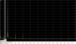
I'm enclosing a spectrum obtained at the output voltage of 1Vrms
From the spectrum, it seems the fundamental is at -15dB, is there some sort of attenuator in between?
FWIW
Filament works only ~ mains freq.
But that's the OP's application.
[*]The two 5532s replaced by 4562, TL071 by OPA627
OPA627 for lower noise?
[*]The 0.047uF polyester caps in the SVO replaced by two matched 0.033uF Wima FKP2
C1 and C4?
[*]The 3K3 resistors replaced by 5K/0.1% glass-encapsulated resistors. I don't know their origin but I know they were used in the precision strain gauge amplifiers made by a company I used to work for.
Guess any 5K 0.1% should do.
[*]Removed the two 100R freq. adj. trimmers, the frequency is now adjusted by trimming R1
You mean resistors R6a and R7b? They are not trimmers, just resistors. At least on the photo.
[*]Added a 22K pot in front of D1/R12 for adjusting the output voltage
Very useful
[*]The FET is now MMBF4091 with the parallel resistor R4 reduced to 500R
Why change that FET?
[*]R3 in the local NFB from the 1st integrator to the inverter is reduced from 147K to 133K
Why?
In my case I will have to modify the circuit for 60Hz.
No attenuator, it is how the software scales the input voltage relative to the full scale of the ADC.From the spectrum, it seems the fundamental is at -15dB, is there some sort of attenuator in between?
Regards,
Braca
No attenuator, it is how the software scales the input voltage relative to the full scale of the ADC.
Regards,
Braca
Then the 3rd's are -(131-15) = -116
Last edited:
OPA627 for lower noise?
There is an active thread with boards available you should go there.
http://www.diyaudio.com/forums/anal...ator-turntable-motor-drive-6.html#post4909928
Last edited:
Very helpful, thank you!
I'm looking forward to it.
I've been playing with this oscillator for a while, and here is the list of changes made so far:
For illustration, I'm enclosing a spectrum obtained at the output voltage of 1Vrms, but please note that this is not the best result I've got - I'm not at home right now and the measurement with the lowest THD was made with another laptop. While the 2nd is the same in that plot (-130dB), the 3rd is at the level of -140dB in the lowest THD spectrum I measured.
- The two 5532s replaced by 4562, TL071 by OPA627
- The 0.047uF polyester caps in the SVO replaced by two matched 0.033uF Wima FKP2
- The 3K3 resistors replaced by 5K/0.1% glass-encapsulated resistors. I don't know their origin but I know they were used in the precision strain gauge amplifiers made by a company I used to work for.
- Removed the two 100R freq. adj. trimmers, the frequency is now adjusted by trimming R1
- Added a 22K pot in front of D1/R12 for adjusting the output voltage
- The FET is now MMBF4091 with the parallel resistor R4 reduced to 500R
- R3 in the local NFB from the 1st integrator to the inverter is reduced from 147K to 133K
The measurements were made with a MOTU Audio Express interface using the SpectrumLab S/W, the sampling rate was 48kHz, FFT length 512K, spectral window was -196dB FlatTop, and the number of FFT averages was 32.
Other artifacts in the spectrum are not due to the oscillator - they come from the SMPS powering the audio interface.
Hope this spares some time in modifying the oscillator.
Regards,
Braca
Now it's my time to be rude. The first and final one.
Why don't you speak for yourself and shut up!
There seems to be nicer folks here that are finding discussing this productive.
Very rude. I agree with Anatech.
I've read the previous 500 pages and he is correct.
Start another thread in Analog Source.
Correct for the spectrum attached.Then the 3rd's are -(131-15) = -116
The one I'm not able to show until I'm back home next week has the 3rd at -140dB.
Regards,
Braca
OPA627 for lower noise? Partly, because replacing the original TL071 with an OPA134 also reduced THD. No difference in THD between the latter and the OPA627, and since I have several of these I saved the 134 for another project.
C1 and C4? No, C1 and C2 on the schematics.
Guess any 5K 0.1% should do. Not quite, the low distortion ones should be preferred.
You mean resistors R6a and R7b? They are not trimmers, just resistors. At least on the photo. They are trimmers on the assembled PCB I received.
Very useful. Yes, should not be without one for a variable output level oscillator.
Why change that FET? Was used in another oscillator (Kleinschmidt), wanted to see if there are effects on the THD level.
Why? R3 has a strong influence on the THD level in this oscillator. The value of 133K appears to be a compromise between THD and the settling time after an output voltage change.
In my case I will have to modify the circuit for 60Hz. Changing the frequency requires changes at several places, and is not a trivial task.
Regards,
Braca
- Home
- Design & Build
- Equipment & Tools
- Low-distortion Audio-range Oscillator