What are the hidden issues?...
I haven't built it yet so I can't comment on all of the performance problems that Samuel has already noted.
My specific concern was about the need to have the Sin and Cos outputs accurately matched.
I plan a manually tunable frequency oscillator, so there will be couple of variable resistor tracks, that potentially will spoil the equality of the Sin and Cos outputs.
I have an idea for a simple feedback system to automatically trim this.
But this means a trim feedback loop to control the leveler feedback loop that controls the oscillator feedback loop - and I haven't simulated that yet.
Be a nice test of my competence in feedback and I still think the sum of squares technique looks neat for my application.
My objective is a little different to Samuel, he wants optimized distortion performance, I need tunability and will have to accept some trade-off.
Best wishes
David
Last edited:
I might be missing something here, but I wonder why it takes so long to calculate an averaged spectrum in your case.Thank you for your questions! I was mistaken. My software was running with the FFT size 524288 (maximum), but the output averaging was not used else. It allows to get noise really down, but needs very long time for to get the result.
For example, calculating an average of 28 spectra with the same length as above from a five-minute record @ 48kHz off-line by means of the Welch overlap-add algorithm costs me less than 5 seconds CPU time on an Intel i7 laptop.
Regards,
Braca
I might be missing something here, but I wonder why it takes so long to calculate an averaged spectrum in your case.
For example, calculating an average of 28 spectra with the same length as above from a five-minute record @ 48kHz off-line by means of the Welch overlap-add algorithm costs me less than 5 seconds CPU time on an Intel i7 laptop.
Regards,
Braca
Maybe he just means the 5 min to take the data.
I might be missing something here, but I wonder why it takes so long to calculate an averaged spectrum in your case.
For example, calculating an average of 28 spectra with the same length as above from a five-minute record @ 48kHz off-line by means of the Welch overlap-add algorithm costs me less than 5 seconds CPU time on an Intel i7 laptop.
Regards,
Braca
With the maximum averaging 100 times, needs approximately 20 minutes for to get the result in the real time measurements.
With the maximum averaging 100 times, needs approximately 20 minutes for to get the result in the real time measurements.
Scott Wurcer was right, it's the acquisition time that is responsible.
It also tallies with my obseravtion, i.e. five minutes acquisition time for 28 averages.
Thank you for your information.
regards,
Braca
Hi Vladimir, did the German company ever produce a commercial version of your VK-1?Hi DDB, richiem and RNMarsh,
Thanks for your kind responses, I'm very glad to communicate with you as specialists highly competent just in low-distortion measurements and generation.
Sooner or later, all my designs will be available for DIY building, I promise that. But now there is also a commercial interest in some of them and at the moment I negotiate with a German company about launching the production of my VK-1,2 instruments.
See my latest article on a state-variable audio oscillator which has a higher potential of reducing distortion than my previous VK-1 device.
Vladimir.
Vladimir.
Last edited:
See my latest article on a state-variable audio oscillator which has a higher potential of reducing distortion than my previous VK-1 device.
Vladimir.
I saw that. Very nice. 🙂
Is there any way we can purchase an operational VK-1 unit or is there any chance of a GB for PCB's so that we could make our own? 😉
Thanks very much for your interest and the kind words!
As mentioned previously, I hope to make PCBs available once the design is proven.
The front panel is engraved by Schaeffer AG (German mother company of Front Panel Express). Likely I can't offer finished front panels, but surely I can make the design file for Front Panel Designer available.
Samuel
Sorry for quoting an old post from almost 12 months ago, I'm wondering if there is any update to this oscillator.
I'm looking forward to build one.
I'm wondering if there is any update to this oscillator.
Thanks for asking; I was about to post an update in the next few days anyway.
There are now several people assembling and testing the second revision of the oscillator main board and front panel PCB. I'm still working on the external power supply; this task got delayed because the power transformer was not delivered to my specifications.
Samuel
A note on power supplies for these sources. The supply Viktor uses on his oscillator provides pretty good noise isolation. I think the real key is that it doesn't connect to the circuit ground at all.
Two events I just went through confirmed this. First I was replacing some failed caps in the "0202" analog interface board for an EMU 1212M. This board has the AK5394A and a Cirrus DAC. I had upgraded the opamps to LME49880 but I noticed the caps were bulging. There are 4 470 uF caps on the ref bias for the ADC. They had deteriorated to about .47uF so replacement was due. With new 470 uF Polymer Electolytic caps (less than 100 mOhm ESR at 1 KHz) I wanted to verify the performance.
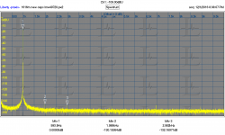
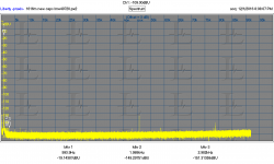
My oscillator array runs on 9V batteries and goes through them pretty quickly. Of course the batteries were dead when I went to test. I had obtained some cheap DC-DC converters from China: LM2587 DC-DC Boost Converter 3V-30V Step up to 4-35V Power Supply Module MAX 5A | eBay $2 ea. to see if I could make this run off of cheaper or rechargeable batteries. So I patched the cheap switcher in with the output at 34V and varying the input from 3.5 to 6V on my bench supply. It all works quite well. The first picture is the distortion residuals of the board at about -130 dB for 2nd and 3rd. This is at the optimum input level (-16 dBFS) and these do vary from channel to channel and chip to chip. The second picture is the full band (20 Hz to 100KHz) and the only spurs are at 52 KHz and 75 KHz. Those are there regardless of the source (and also on the 1616M) so I think they are not related to the source. However no power supply noise anywhere to be found. The notes on the supply say its switches at 100 KHz so there may be some higher frequency junk but its not showing anything in this measurement. I ordered some AC-DC 30V supplies ($3 ea) so see how well they work. Basically I'm less reluctant to use switchers now than before.
Two events I just went through confirmed this. First I was replacing some failed caps in the "0202" analog interface board for an EMU 1212M. This board has the AK5394A and a Cirrus DAC. I had upgraded the opamps to LME49880 but I noticed the caps were bulging. There are 4 470 uF caps on the ref bias for the ADC. They had deteriorated to about .47uF so replacement was due. With new 470 uF Polymer Electolytic caps (less than 100 mOhm ESR at 1 KHz) I wanted to verify the performance.
My oscillator array runs on 9V batteries and goes through them pretty quickly. Of course the batteries were dead when I went to test. I had obtained some cheap DC-DC converters from China: LM2587 DC-DC Boost Converter 3V-30V Step up to 4-35V Power Supply Module MAX 5A | eBay $2 ea. to see if I could make this run off of cheaper or rechargeable batteries. So I patched the cheap switcher in with the output at 34V and varying the input from 3.5 to 6V on my bench supply. It all works quite well. The first picture is the distortion residuals of the board at about -130 dB for 2nd and 3rd. This is at the optimum input level (-16 dBFS) and these do vary from channel to channel and chip to chip. The second picture is the full band (20 Hz to 100KHz) and the only spurs are at 52 KHz and 75 KHz. Those are there regardless of the source (and also on the 1616M) so I think they are not related to the source. However no power supply noise anywhere to be found. The notes on the supply say its switches at 100 KHz so there may be some higher frequency junk but its not showing anything in this measurement. I ordered some AC-DC 30V supplies ($3 ea) so see how well they work. Basically I'm less reluctant to use switchers now than before.
Attachments
A note on power supplies for these sources. The supply Viktor uses on his oscillator provides pretty good noise isolation. I think the real key is that it doesn't connect to the circuit ground at all.
Two events I just went through confirmed this. First I was replacing some failed caps in the "0202" analog interface board for an EMU 1212M. This board has the AK5394A and a Cirrus DAC. I had upgraded the opamps to LME49880 but I noticed the caps were bulging. There are 4 470 uF caps on the ref bias for the ADC. They had deteriorated to about .47uF so replacement was due. With new 470 uF Polymer Electolytic caps (less than 100 mOhm ESR at 1 KHz) I wanted to verify the performance.
My oscillator array runs on 9V batteries and goes through them pretty quickly. Of course the batteries were dead when I went to test. I had obtained some cheap DC-DC converters from China: LM2587 DC-DC Boost Converter 3V-30V Step up to 4-35V Power Supply Module MAX 5A | eBay $2 ea. to see if I could make this run off of cheaper or rechargeable batteries. So I patched the cheap switcher in with the output at 34V and varying the input from 3.5 to 6V on my bench supply. It all works quite well. The first picture is the distortion residuals of the board at about -130 dB for 2nd and 3rd. This is at the optimum input level (-16 dBFS) and these do vary from channel to channel and chip to chip. The second picture is the full band (20 Hz to 100KHz) and the only spurs are at 52 KHz and 75 KHz. Those are there regardless of the source (and also on the 1616M) so I think they are not related to the source. However no power supply noise anywhere to be found. The notes on the supply say its switches at 100 KHz so there may be some higher frequency junk but its not showing anything in this measurement. I ordered some AC-DC 30V supplies ($3 ea) so see how well they work. Basically I'm less reluctant to use switchers now than before.
Are there switcher around that operate closer to 1MHz. I'd feel better about that than 100kHz.
LT3471 operates at 1.2MHz.
Nice part.
Do they have one that does +/- 15V
From datasheet page 1:
"The LT3471 switches are rated at 42V, making the device ideal for boost converters up to ±40V as well as SEPIC and flyback designs."
"The LT3471 switches are rated at 42V, making the device ideal for boost converters up to ±40V as well as SEPIC and flyback designs."
The LT4371 looks really interesting but lacks one quality I would like- transformer isolation for the output. It has another challenge- human hostile package.
I have one of Jan Didden's silen switchers here. I'll see what its doing in this application.
I have one of Jan Didden's silen switchers here. I'll see what its doing in this application.
Again, a human hostile package but otherwise well suited to this application https://datasheets.maximintegrated.com/en/ds/MAX13253.pdf I wish some intrepid China vendor would watch these discussions and just build what we need. I can't make a PCB for what they want for the complete unit.
The LT4371 looks really interesting but lacks one quality I would like- transformer isolation for the output. It has another challenge- human hostile package.
I have one of Jan Didden's silen switchers here. I'll see what its doing in this application.
I have one too. I'll fire it up on the SVO core and see how it does but there isn't quite enough current to run the whole oscillator.
The LT4371 looks really interesting but lacks one quality I would like- transformer isolation for the output. It has another challenge- human hostile package.
I have one of Jan Didden's silen switchers here. I'll see what its doing in this application.
Might still be able to add a transformer in or perhaps buffer it with a DC to DC convertor.
- Home
- Design & Build
- Equipment & Tools
- Low-distortion Audio-range Oscillator