Well, how this transformed from a "Low-distortion Audio-range Oscillator" thread onto a DC-DC conversion one?
I am looking for a low-distortion oscillator than can output at least very low-distortion 60Hz and 81Hz, which I can use as the heart of a turntable electronic supply.
A digital chip might do the job, but setup should be easy. No programming, please! Something like a "digital XR2206" might work.
Anny suggestions?
Well, how this transformed from a "Low-distortion Audio-range Oscillator" thread onto a DC-DC conversion one?
I am looking for a low-distortion oscillator than can output at least very low-distortion 60Hz and 81Hz, which I can use as the heart of a turntable electronic supply.
A digital chip might do the job, but setup should be easy. No programming, please! Something like a "digital XR2206" might work.
Anny suggestions?
Because power supplies are a component of low distortion oscillators.
Because power supplies are a component of low distortion oscillators.
You are too nice. I would have rudely suggested he actually read the thread and see that his answers can be found here.
But there is no need to be rude. It just doesn't matter or help.
I'm too busy with my projects to care anyway.
I'm too busy with my projects to care anyway.
Reading 551 pages? Don't you think it's bit too much?
Simon, I've been around this forum since 2001, you came in 2008. If people didn't want to help just didn't say anything. This is a place where people collaborate with each other, and I hope it stays that way. I don't want to be rude either, or my answer would be a different one.
Now about power supplies being part of low distortion oscillators, I am looking for oscillators to be the source of power supplies.
Well, how this transformed from a "Low-distortion Audio-range Oscillator" thread onto a DC-DC conversion one?
I am looking for a low-distortion oscillator than can output at least very low-distortion 60Hz and 81Hz, which I can use as the heart of a turntable electronic supply.
A digital chip might do the job, but setup should be easy. No programming, please! Something like a "digital XR2206" might work.
Anny suggestions?
Yes, I would think an mp3 stick with a full side (30min) of 60Hz, a small PA and a 12.6V filament transformer turned backwards would work fine. Back in 1968 or so one of the mags did an article where a telescope clock drive was driven from a simple oscillator and backwards transformer. You hardly need heroic THD to outdo the mains. Make the channels anti-phase and drive the transformer differentially. You have the benefit of the TT stopping by itself.
BTW as a curious aside I tried the worst mp3 rate and found it to preserve frequency exactly.
Last edited:
The turntable application is a natural for a state variable oscillator. I have designed two for products from Rockport. Infinitely low distortion doesn't help because the magnetic structures are not perfect. My last effort was based on current drive to reduce higher order resonances in the motor.
I would start with this: Assembled Low Distortion Audio Range Oscillator 1KHz Sine Wave Signal Generators | eBay . I could not make a PCB for that price. I received two and will be testing them shortly. Take the sine and cosine outputs into a chipamp PCB and matching transformers and you could be there for a pretty modest cost. My design needed some special features. I found that the two phases should be independently adjustable to get the lowest vibration. I used two oscillators and trims on each output. I also had a 10 second full drive for startup (those platters are heavy). I hope this helps.
I would start with this: Assembled Low Distortion Audio Range Oscillator 1KHz Sine Wave Signal Generators | eBay . I could not make a PCB for that price. I received two and will be testing them shortly. Take the sine and cosine outputs into a chipamp PCB and matching transformers and you could be there for a pretty modest cost. My design needed some special features. I found that the two phases should be independently adjustable to get the lowest vibration. I used two oscillators and trims on each output. I also had a 10 second full drive for startup (those platters are heavy). I hope this helps.
Hi Scott.
A friend of mine suggests exactly that arrangement you mentioned. But I prefer a metal box holding it all.
As I would need a power amp to feed the AC transformer, using mains AC for the amp would demand AC input for it too.
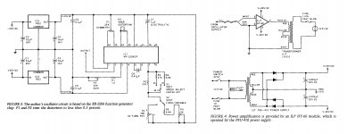
This is the arrangement I'm thinking of, based on a Gary Galo's project from '86 in The Audio Amateur.
My idea is to find an oscillator with lower distortion to feed into the amp. Analog or digital.
A friend of mine suggests exactly that arrangement you mentioned. But I prefer a metal box holding it all.
As I would need a power amp to feed the AC transformer, using mains AC for the amp would demand AC input for it too.
This is the arrangement I'm thinking of, based on a Gary Galo's project from '86 in The Audio Amateur.
My idea is to find an oscillator with lower distortion to feed into the amp. Analog or digital.
Attachments
I would start with this: Assembled Low Distortion Audio Range Oscillator 1KHz Sine Wave Signal Generators | eBay . I could not make a PCB for that price. I received two and will be testing them shortly. Take the sine and cosine outputs into a chipamp PCB and matching transformers and you could be there for a pretty modest cost. My design needed some special features. I found that the two phases should be independently adjustable to get the lowest vibration. I used two oscillators and trims on each output. I also had a 10 second full drive for startup (those platters are heavy). I hope this helps.
These ones might work even better, but they need programming (which I know nothing about) to see the output frequencies.
Why do I need two transformers, for sine and cosine? The project I showed above doesn't need that.
The transformer for MAX 13253 is Halo at Mouser for $9 each.
https://www.haloelectronics.com/pdf/discrete-dc2dc-8pin1a.pdf
THx-RNMarsh
https://www.haloelectronics.com/pdf/discrete-dc2dc-8pin1a.pdf
THx-RNMarsh
Last edited:
And that transformer would move the Thorens motor?
I doubt those cores will do 60Hz, I mentioned surplus 12.6 because it was designed for 60Hz you just need a power rating (and it's a couple of bucks). The Hurst motor I had was 15W.
Sorry, forgot to put the URL for the LT DAC1282, which is a sinusoidal low frequency generator:
DAC1282 | Precision DAC (=<10MSPS) | Digital to Analog Converter | Description & parametrics
It needs programming though.
Filament transformers do not seem to work driven by amplifiers: the chips or transistors overheat and burn. The transformers have to be toroidal.
It's there that I said the setup gets large and expensive.
I would start with this: Assembled Low Distortion Audio Range Oscillator 1KHz Sine Wave Signal Generators | eBay . I could not make a PCB for that price. I received two and will be testing them shortly. Take the sine and cosine outputs into a chipamp PCB and matching transformers and you could be there for a pretty modest cost. My design needed some special features. I found that the two phases should be independently adjustable to get the lowest vibration. I used two oscillators and trims on each output. I also had a 10 second full drive for startup (those platters are heavy). I hope this helps.
What matching transformers types are you thinking about? As I said above, for the load to work with the chip amps, the transformers have to be toroidal.
The Thorens would need two 16v AC outputs to feed each phase.
In the Galo's supply, the phase split was still done with capacitors. What you changed was the 110v supply, which was now electronically controlled 60Hz.
Reading 551 pages? Don't you think it's bit too much?
Simon, I've been around this forum since 2001, you came in 2008. If people didn't want to help just didn't say anything. This is a place where people collaborate with each other, and I hope it stays that way. I don't want to be rude either, or my answer would be a different one.
Now about power supplies being part of low distortion oscillators, I am looking for oscillators to be the source of power supplies.
Page 1 has enough information to build a low distortion oscillator. If you want to start a thread on your entire project that might be productive for many, not just folks here.
Filament transformers do not seem to work driven by amplifiers: the chips or transistors overheat and burn. The transformers have to be toroidal.
I don't see how that would happen without some parasitic oscillation causing it. This can be worked around. The telescope drive worked with a Radio Shack filament transformer.
Hi carlmart,
-Chris
Not true. Why would you say that? EI core transformers can work just fine at those and even higher frequencies. The core inductance needs to go up at lower frequencies. So as long as the transformer is designed for the frequencies you are running at, either type will do just fine.The transformers have to be toroidal.
-Chris
These ones might work even better, but they need programming (which I know nothing about) to see the output frequencies.
Why do I need two transformers, for sine and cosine? The project I showed above doesn't need that.
For two speeds you need the two drives for the motor at 90 degrees. You can switch caps and other kludges but 2 phase drive is a cleaner solution. Any filament transformer would work. There are lots o options on ebay.
Resetting the oscillators is a matter of scaling the caps for the target frequency. Something like .01 uF to .22 uF for the two tuning caps (in head arithmetic so its not really correct) and the AGC needs to be larger as well.
You don't need 120V to spin the motor either but you do need more for 81 than for 60.
We should move this to a new thread. If so I'll dig out the schematics for the two I have done. One was to replace a digital solution that had a big EMI problem.
Page 1 has enough information to build a low distortion oscillator. If you want to start a thread on your entire project that might be productive for many, not just folks here.
Now it's my time to be rude. The first and final one.
Why don't you speak for yourself and shut up!
There seems to be nicer folks here that are finding discussing this productive.
- Home
- Design & Build
- Equipment & Tools
- Low-distortion Audio-range Oscillator