Hi Pete,
I agree, but this would be a mammoth job for anyone.
-Chris
Please, people! This thread started as a discussion about Roger Rosen's Phase Shift Oscillator and if the subject shifts to 339 mods or whatever start a new thread. There are over 5000 posts in this thread making it hard to find things, even just to figure out where the discussion has gone.
Hi David,
Your image doesn't expand when I click on it, so I can't see what it is easily.
Hi Demian,
I am now resigned to the knowledge that I need to pick up a Shibasoku THD meter / analyser or similar. The work I just did on a Marantz 2325 has readings very close to the residual noise on my 339A (amp only). I didn't expect this performance, yet here it is. These should be 6 dB worse easily. It would be nice to be able to see what is buried in the noise.
-Chris
Not worth expanding. I put that up there to support you point about price.
It sure would be nice to break off threads that discuss specific equipment mods. I had to work backwards for about 15 minutes just to figure out what was being discussed here.
We did but far too late in the thread.
For those of us who might not have the knowledge or background as y'all,
can you explain what the extra bandwidth get's us?
From the AD797 with 8 MHz
vice the ADA4896 with 65 MHz?
Does it mean an increase in stability when we used it in the audio band?
Or
does it mean an opportunity for more noise and RF to enter the circuit
creating havoc?
Sync we want more loop gain above the fundamental what ever that is. With op amps a greater GBP gets us this. But your point is well taken about the additional noise in a wider BW. The other way to get greater loop gain is to use very specialized/tailored compensation.
With the absence of uncompensated op amps that leaves composite or discrete amplifiers.
The problem with composites is the gain is so high the amplifier become difficult to work with particularly at overload/clipping etc. Not impossible but what we have to do to stablize a composite digs into the performance.
With discrete amplifiers it's possible to design an amplifier tuned for the purpose. A journey into RF design would be helpful with this. Since such an amplifier is for instrumentation we don't need to be concerned with how it will sound.
Please, people! This thread started as a discussion about Roger Rosen's Phase Shift Oscillator and if the subject shifts to 339 mods or whatever start a new thread. There are over 5000 posts in this thread making it hard to find things, even just to figure out where the discussion has gone.
I hoping with the new proposed forum software a better search engine will also be included.
Rather than simply new threads perhaps sub threads as well.
Hi David,
That would be pretty cool.
As far as I know, it would take a human to pull posts for each topic. That's the problem when you have a thread that runs properly that involves intelligent people. Lot's of really great stuff all mixed together. I wonder how much is the result of cross-pollination between our learned members. Ideas being applied to other problems spontaneously.
-Chris
Hi David,
That would be pretty cool.
As far as I know, it would take a human to pull posts for each topic. That's the problem when you have a thread that runs properly that involves intelligent people. Lot's of really great stuff all mixed together. I wonder how much is the result of cross-pollination between our learned members. Ideas being applied to other problems spontaneously.
-Chris
Yes the use of sub threads would allow for this while maintaining the thesis of the thread.
This is one of the longest running threads near five years. We didn't think about what it would be like to try and navigate this far down the road.
Do you have a possibility to increase the FFT resolution? This can also be used to see a small signal in the noise. What FFT size are you using?
Thank you for your questions! I was mistaken. My software was running with the FFT size 524288 (maximum), but the output averaging was not used else. It allows to get noise really down, but needs very long time for to get the result. Maybe overnight... 🙂
Now with the 30 (maximum is 100) times averaging, I can see noise floor around -170dB, some spikes from unknown sources around -160dB and the third harmonic at -166dB when the oscillator runs with the polystyrene capacitor. Maybe deep in the night I can get a better picture.
Hi David,
I don't think anyone would have expected a five year (so far) run without chaos.
Let's see what features are available with the new software
-Chris
I don't think anyone would have expected a five year (so far) run without chaos.
Let's see what features are available with the new software
-Chris
Thank you for your questions! I was mistaken. My software was running with the FFT size 524288 (maximum), but the output averaging was not used else. It allows to get noise really down, but needs very long time for to get the result. Maybe overnight... 🙂
Now with the 30 (maximum is 100) times averaging, I can see noise floor around -170dB, some spikes from unknown sources around -160dB and the third harmonic at -166dB when the oscillator runs with the polystyrene capacitor. Maybe deep in the night I can get a better picture.
The long FFT's are problematic. The RC oscillator drifts enough to move off of the bin. I think your bins at 500K are around 1/4 Hz so you need the oscillator to be stable to 1/8 Hz for the entire duration of the measurement. I know they move 1-2 Hz during warmup. I tried the ultra high res measurements and in some cases the fundamental and harmonics were smeared across several bands. it gave great but impossible low distortion except that the fundamental was 10 dB low.
External locking to a precision source would help if it didn't degrade the oscillator. I have not been successful with that yet. Hum and harmonics creep in in all the experiments I have tried.
Yes, I understand this problem. Measurements must be done after the long warm up, but anyway results may not so precise. Maybe needs to do the level measurement verification. As example - fundamental's level also may be smeared, and we can compare this level's averaged measurement with measurement without long averaging, or measurement with a voltmeter. Then averaged levels can be corrected...The long FFT's are problematic. The RC oscillator drifts enough to move off of the bin. I think your bins at 500K are around 1/4 Hz so you need the oscillator to be stable to 1/8 Hz for the entire duration of the measurement. I know they move 1-2 Hz during warmup. I tried the ultra high res measurements and in some cases the fundamental and harmonics were smeared across several bands. it gave great but impossible low distortion except that the fundamental was 10 dB low.
External locking to a precision source would help if it didn't degrade the oscillator. I have not been successful with that yet. Hum and harmonics creep in in all the experiments I have tried.
Last edited:
The problem of oscillator frequency variation smearing the spectral peaks of the harmonics can be dealt with by pre-processing the signal acquired in a suitable manner.The long FFT's are problematic. The RC oscillator drifts enough to move off of the bin. I think your bins at 500K are around 1/4 Hz so you need the oscillator to be stable to 1/8 Hz for the entire duration of the measurement. I know they move 1-2 Hz during warmup. I tried the ultra high res measurements and in some cases the fundamental and harmonics were smeared across several bands. it gave great but impossible low distortion except that the fundamental was 10 dB low.
External locking to a precision source would help if it didn't degrade the oscillator. I have not been successful with that yet. Hum and harmonics creep in in all the experiments I have tried.
I developed such a method in a different application area, but it is equally applicable to the present case. Basically, the procedure consists of three steps:
1. Identify the fundamental frequency variation with time by the so-called parametric spectral analysis
2. Resample the original data in software in terms of the varying fundamental frequency, making thus thee latter the sampling clock
3. Perform the spectral analysis (FFT) as usual, but note that the results obtained will not be in terms of frequency, but rather in terms of the harmonic number (which is exactly what we need for THD estimation)
The procedure is rather involved at the development level, but it could be coded as a stand-alone program. I did it in Matlab, but I guess it can also be realized in Python.
I described the method in a paper presented at a conference last year.
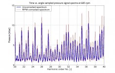
As an illustration I'm enclosing a result from the paper, showing a comparison of the corrected and uncorrected spectra in a particular case. The problem at hand was to determine as accurately as possible the amplitudes of high-order (20th to 40th order, some THD!) pressure pulsations at the exhaust of a large Diesel engine in presence of the fundamental (crankshaft speed) varying between 11.34 and 11.48Hz.
Obviously, the corrected spectral peaks(red lines ) are sharper and have higher, i.e. more accurate, amplitudes.
I'm a bit busy at the moment, but I'll try to apply the method to the Chinese oscillator mentioned earlier in my posts.
Regards,
Braca
Attachments
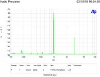
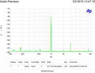
For what it is worth here are my measurements on the Xicon 1/4 watt metal film resistors and the Dale CMF series.
Was this the brown Dale or the blue Dale CMF?
The problem of oscillator frequency variation smearing the spectral peaks of the harmonics can be dealt with by pre-processing the signal acquired in a suitable manner.
On the hardware end I suppose you could generate the sampling clock from the oscillator. Unfortunately I don't think any SRC's have low enough THD.
For what it is worth here are my measurements on the Xicon 1/4 watt metal film resistors and the Dale CMF series.
Those are much higher than I got with the CLT-1. I usually see -165 + for the 3rd harmonic. What power level are you using?
Those are much higher than I got with the CLT-1. I usually see -165 + for the 3rd harmonic. What power level are you using?
Relative scale and of course depends on power level. Mine are at 1/4 rated power.
On the hardware end I suppose you could generate the sampling clock from the oscillator. Unfortunately I don't think any SRC's have low enough THD.
This is probably the SOTA in SRC: http://www.akm.com/akm/en/file/datasheet/AK4137EQ.pdf at -150 dB. Since the measurement would be post filter its not as important. The neat thing about Japanese engineering is that if a number is identifiable there seems to be a focus on getting the best numbers. THD in amps in the 70's and 80's and here THD in a SRC.
The Shibasoku analyzer also locks to the fundamental and and drives the conversions from it. The harmonics are always fixed. The PLL to make that work is pretty involved with a 4 decade range.
Forgot this was post notch so it should be easy at just 1 frequency like 1K. Just a 96X PLL for instance?
- Home
- Design & Build
- Equipment & Tools
- Low-distortion Audio-range Oscillator