I realized I have been looking at the filter as high pass so its a different case and far more sensitive to impedance imbalance. And no beneficial filtering. I'm attaching a passive solution that should be realizable. The inductor should be large but could be powdered iron cup cores based on the CLT-1 realization. Just make it pretty large.
I do recommend Nuhertz Filter Free for this.
I do recommend Nuhertz Filter Free for this.
Attachments

that would be impractical, the same as twin-T due to a trimming is involved. What about 150mH size and EMI immunity? 600ohm in and out? At the same time, <$5 a trivial S-K LPF(MFB LPF even better) will beat that with kilo ohms input and zero ohms output..
I prefer the MFB because you have at least the RC out front. I have seen very high frequency stuff go right through Sallen-Key filters.

guys, seems we are at the same ordinates but at different floors. I'm talking about the nearly perfect sine-source for an audio measurement i.e. BW 20-20k, harmonics -150db and lower. The THD -80db oscillator, or some HF content worrying, that's offtopic as I think.
Do you have a specific type in mind for the resistor? Is the TC critical?The Viking 0207MELF is the best, in that LPF I used 2 in serial but 1pcs is ok up to 10Vrms(simply zero VCR). Caps are more sensitive regarding the VCC, so better to go with 100-250V rated C0G and 2pcs in serial. OPA2156 a bit better vs 1612 as well.
Did you compare them to similar types from e.g., Vishay?
The Viking resistors may be more difficult to source.
Did you try the OPA1656 instead of the OPA2156? In simulation the noise is lower, but the distortion can of course not be simulated.
It has a higher bandwidth, which may be a benefit.
I did not find Vishay here and tested only Susumu and Viking, I did not notice if TCR mattered but I used 50PPM. BTW, the noname thru-hole(same sized as 0207 MELF) type of resistors is also quite ok, isn't the same spectacular as Viking but the tech behind both is the same - thin-metal a long spiral.
I don't know about what circuit you are talking but as a TT notch buffer 2156/1656 look similar.
I don't know about what circuit you are talking but as a TT notch buffer 2156/1656 look similar.
@JensH You can get Viking 0207 MELF resistors via TME.eu (Transfer Multisort Elektronik) from Poland. TME also stocks Vishay MELFs (MMA/SMM0204 and MMB0207). The Vishay MELFs are made in Germany and availability over German and European distributors is quite decent as far as I can tell. European distributors in general mostly stock Vishay, Vitrohm or Viking MELFs - I personally prefer Vishay but don't have any data to back up my preference.
IVX and kn0ppers,
thanks for your feedback.
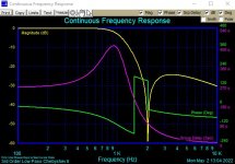
I simulated the MFB filter with a 1 kHz cut-off. I used TINA TI.
The output noise over a 20 kHz BW was found to be 1.77 uV for the OPA2156 and 1.38 uV for the OPA1656.
thanks for your feedback.
I simulated the MFB filter with a 1 kHz cut-off. I used TINA TI.
The output noise over a 20 kHz BW was found to be 1.77 uV for the OPA2156 and 1.38 uV for the OPA1656.
Oh, I forgot to call the ref voltage 5V for 1.77uV to get -129db 😉 but who can stop you to add some gain stage before the LPF to get 6db profit(THD+N -135db!) with 10Vrms output? It will be just 5Vrms for each opamp in a differential LPF.
1audio, a common mode component should be reduced by the nature of differential topology(two LPF, two outputs, and inputs). Also, very important the opamp used in such an LPF, -100db is probably lm353 level. It is Sallen-Key as is, the schematics are in any school book, no any tricks only not typically low impedance.
This has been much discussed here and elsewhere before, so you guys probably already know this.
I think you can get similar results in a Sallen-Key filter by changing the feedback path around the unity gain opamps. The impedance presented to both the inverting and non-inverting inputs of the opamps needs to be the same so that the common mode effects cancel.
See page 5.107 >> https://www.analog.com/media/en/tra...ks/Op-Amp-Applications/Sections5-5-to-5-8.pdf
You'd think that. Assuming you believe the data sheets.CG, in the case, if the issue is an input capacitance modulation, OPA1642 should be the best choice, isn't it?
But.. not really 😉
There are papers available on the internet that describe the common mode distortion caused by the tail current source for the input pair, too.
All I can say is that I've found that you get lower distortion for non-inverting amplifiers that employ overall feedback when the impedances presented to the two input terminals are matched. Even with bipolar designs. And, no - I didn't save the plots and measurements. Once something is optimized best I can, I tend to move on. But, I am not an audio professional, so what I say or think only really applies to me. Just offering an observation...
I don't want to say that your paper on the page 5.107 is wrong, I just recollect the story when I asked johnc124
to recommend me some Ti opamp suitable for the buffer after a notch-filter role better than opa2156. He offered the opa1642 because of constant input capacitance, I did try that and got a worse result than OPA1612, OPA2156, OPA1656, and so on.
to recommend me some Ti opamp suitable for the buffer after a notch-filter role better than opa2156. He offered the opa1642 because of constant input capacitance, I did try that and got a worse result than OPA1612, OPA2156, OPA1656, and so on.
As I said, assuming you believe...I don't want to say that your paper on the page 5.107 is wrong, I just recollect the story when I asked johnc124
to recommend me some Ti opamp suitable for the buffer after a notch-filter role better than opa2156. He offered the opa1642 because of constant input capacitance, I did try that and got a worse result than OPA1612, OPA2156, OPA1656, and so on.
However, I certainly believe your results. You did the tests, after all. I bet my belief certainly made your day. 🙂
Remember all opamps are a trade out of features and performance. and the performance of the OPA1656 is exceptional for a CMOS opamp. it may not be the best solution for this application or maybe some aspect was not optimal for the active filter.
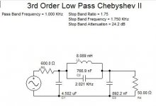
I attached a pretty realistic 600 Ohm in (works with opamps) 50 Ohm out for low noise passive filter. The values are not crazy and may require a little tuning to get the null on HD2 if that is important. Suitable inductors are not that expensive ($3-$12) so its not crazy. It is another way to get there and the best instruments made (CLT1 & CLT10) use this technique to get the performance, -170 dB HD3.
For my purposes Viktor's oscillators are excellent and just work. You are starting with a typical -150 dB harmonics which is more that good enough for most any application.. You can always apply John Curl's simple enhancement- add a cap across the output to knock the harmonics down further. Just use a very good cap, film or COG, so its not limiting your efforts.
Attachments
First of all, I repeat my testing with opa1656 in SK LPF configuration, where I get abnormal +10 dB THD-3. Two OPA pieces.Remember all opamps are a trade out of features and performance. and the performance of the OPA1656 is exceptional for a CMOS opamp. it may not be the best solution for this application or maybe some aspect was not optimal for the active filter.
I attached a pretty realistic 600 Ohm in (works with opamps) 50 Ohm out for low noise passive filter. The values are not crazy and may require a little tuning to get the null on HD2 if that is important. Suitable inductors are not that expensive ($3-$12) so its not crazy. It is another way to get there and the best instruments made (CLT1 & CLT10) use this technique to get the performance, -170 dB HD3.
I missed that initial testing was done with +-5 V (10 V total). And when I bring power up to +-9 ( 18V ) the issue is disappear. Strange things that OPA DS states min. 4.5V. Signal level wasn't too high 2Vp-p, so with 10V I had about 4V head-room on both power lines. I don't have opa2156 (and no stock at mouser) so can't say how it would works. But if someone could re-test SK using lower than +-15V I 'd like to be notified. And, please, do not use 220uF electrolytic at the inputs w/o safety current limiting resistors, other-ways OPA unlikely to survive first try.
The problem with modern OPA that it's much more complex devices compare to old JFET OPA, where input capacitance variation vs common input voltage was the ONLY problem. They stop to picture internal circuits, but when I see "feedforward " stages running in parallel to usual signal path, I could imagine auxiliary circuitry that more advanced than main OPA itself.
Inductors with any ferromagnetic core generate up to 1% THD, so stop dreaming. Air-core only, but size and weight -😵
Figure 10 in the datasheet indicates that there is such a problem at low supply voltages. At 1 Vpp it looks OK, but at 5 Vpp there is higher distortion with a supply of +/-5 V. The figure shows THD+N, so some of the information about the THD is buried in the noise.First of all, I repeat my testing with opa1656 in SK LPF configuration, where I get abnormal +10 dB THD-3. Two OPA pieces.
I missed that initial testing was done with +-5 V (10 V total). And when I bring power up to +-9 ( 18V ) the issue is disappear. Strange things that OPA DS states min. 4.5V. Signal level wasn't too high 2Vp-p, so with 10V I had about 4V head-room on both power lines.
So your 2 Vpp may start to hit som non-linear region as well.
It is indeed strange that it is specified for operation down to +/-2.25 V. With such a low supply voltage the common mode input range only allows inputs from 0 V down to -2.25 V. And performance curve sare only shown for supply voltages of+/-5 V and up, except for the quiescent current, which is specified from 0 to 36 V.
- Home
- Design & Build
- Equipment & Tools
- Low-distortion Audio-range Oscillator