I have the FreeUSBi programmer that supports both I2C and SPI communication. I also have the Nvarcher 1452 DSP board w/o the codec board. According to previous posts this board uses SPI for DSP communication. The 1452 board specifies 5 lines for SPI: Gnd, MOSI, MISO, CS and CLK. My question is which of the 10 FreeUSBi lines are connected to the five 1452 DSP lines. I found the attached diagram from an Analog Devices document. It defines the SPI lines except Chip Select (CS). Is pin 9 (SS bar) the CS line?

Hi , This is the working connection with the Free USBi . If you want to save your configuration in internal EEPROM The jumper next to the cables SIP 1 has to be transfered to 1-2 restart /LED changes the color / and Go in Hardware windows SPI 0x 1 ADR {0} , right click on small ADAU 1452/IC 1 window {not on the text but next to it/ - Self Boot Memory - Write Last Compilation through DSP and choose SP 0 or SP3 /works with mine/. The project supplied above is working fine. I cant figure out only how to change the frequency from 192khz to 96 /for 2x computation speed/ . I can change it but all frequency dividers are doubled 🙂
Yeah I've given up on these. They are just bad boards that do not work out of the factory - crap. Spend more money, and less of your time, on other boards 🙂
For anyone interested in a reasonably priced USBi clone, I can recommend this one ($23.28 at the time of this posting)...
https://www.aliexpress.us/item/3256805426472835.htm
I took a risk on buying it because I can't find any other sellers with this exact device, no one else had purchased it yet, there is no product description, and the seller doesn't have the best reviews. My PC instantly recognized it though. Connected it to a Mediaworks 1466 board and it communicates with the core and EEPROM perfectly over SPI using SigmaStudio 4.7.
I opened the shell and the top of the board is covered in epoxy, of course. Back of the board is labelled "ADI USBi_V4".
Not sure I even want to proceed with my planned project now though. My brain turned to goo when messing with SigmaStudio to try and figure out how to set this board up. Considering just buying a completed ADSP-21489 Audio Processor from Ali instead.
Sorry, copy and paste error. Chopped off the l in html...
https://www.aliexpress.com/item/3256805426472835.html
https://www.aliexpress.com/item/3256805426472835.html
I see "Video unavailable. This video has been removed by uploader". When you go to the hardware configuration tab is your USB configuration green?I have ordered a second board , and it's just the same : no control via SigmaStudio.
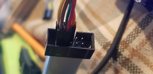
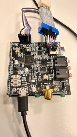
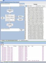
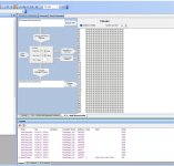
I have attached a picture to show the connections. And a movie , that I can control the Standard ADAU1452 Eval Board from ADI.
Several issues to pay attention to:
1. Ensure that the device can be found under the computer system equipment/universal serial control bus
 ,On the software configuration page, you can see that USBI is green,

2.Press F7 and the ADAU1452 DSP board LED will change. 3. Enter the write page and do not change the EEPROM

1. Ensure that the device can be found under the computer system equipment/universal serial control bus
2.Press F7 and the ADAU1452 DSP board LED will change. 3. Enter the write page and do not change the EEPROM
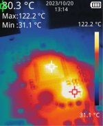
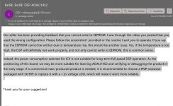
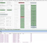
Thank you for your explanation, However, you have not noticed that the screenshots show that I applied the procedure correctly EEprom written.. And I also appreciate your transparency during our email exchange. The settings you specify are the default settings offered when we create a new project. And it turns out that even with these parameters we notice difficulties, it becomes impossible to read the eeprom or even sometimes to write to it, I showed you the heating of certain components and your answer to was honest, but I believes that the community as a whole should have the opportunity to know the causes, and as a result the appropriate measurements will be corrected on your cards.
Attachments
Last edited:
Yes indeed be careful, wanting to show the problems encountered by the heating of the card, in a video without revealing my project, I got trapped by using a project available on the internet and whose parameters are not correct. The consequences being the same as those caused by excessive temperature did not alert me to the configuration errors of the project that I downloaded. So good lesson, check the parameters in the projects available on the internet.
I was reading that quite some people are having issues with these ADAU1452 boards.
This one in particular:

Somebody on another forum also couldn't load any programs in.
Although it seems that the DSP is connected.
The following is worth a try (I don't have one of these boards atm, so can't test it by myself)
I have worked with these ADAU145x DSP's quite a bit in the past, so this reminded me of two things.
1 - either selfboot mode is not enabled
2 - EEPROM is not working properly (fails to write or something)
So I also found the GERBER view from the top layer online;

According the datasheet, we are looking for pin 34 at the DSP IC:
So following the traces from pin 34, it goes trough the SIP1 header and than R7 to (I assume) 3V3.
So this part seems to be correct.
For the 2nd issue, we have to focus around IC5.
The write protect is on PIN7.
According to the datasheet of the EEPROM;
Pin7 from IC5 is connected to R120 and R121.
R120 is a resistor connected to 3V3.
However, R121 doesn't seem to be populated!
In other words, according to this picture and GERBER view, the EEPROM is in always write protect mode.
Shortening the pins of R121 will put the EEPROM in write mode, needed while writing.
Or one can just solder a little wire from the connection between R120+R121 to bottom leg of jumper CN5 (the one with the number "9" next to it).
According to the information I have, it seems they populated the wrong position, they should have populated IC7 instead, which is directly connected to the write protect jumper CN5.
No idea if this will solve problems, but purely on paper, this shouldn't work as it is now.
This one in particular:
Somebody on another forum also couldn't load any programs in.
Although it seems that the DSP is connected.
The following is worth a try (I don't have one of these boards atm, so can't test it by myself)
I have worked with these ADAU145x DSP's quite a bit in the past, so this reminded me of two things.
1 - either selfboot mode is not enabled
2 - EEPROM is not working properly (fails to write or something)
So I also found the GERBER view from the top layer online;
According the datasheet, we are looking for pin 34 at the DSP IC:
Self Boot Select. This pin allows the device to perform a self boot, in which it loads its RAM and
register settings from an external EEPROM. Connecting Pin 34 to logic high (IOVDD) initiates a
self boot operation the next time there is a rising edge on Pin 24 (RESET). When this pin is
connected to ground, no self boot operation is initiated. This pin can be connected to IOVDD
or to ground either directly or pulled up or down with a 1.0 kΩ or larger resistor.
So following the traces from pin 34, it goes trough the SIP1 header and than R7 to (I assume) 3V3.
So this part seems to be correct.
For the 2nd issue, we have to focus around IC5.
The write protect is on PIN7.
According to the datasheet of the EEPROM;
Write-Protect (WP)
The write-protect input, when connected to GND, allows normal write operations. When the WP pin is connected
directly to VCC, all write operations to the protected memory are inhibited.
Pin7 from IC5 is connected to R120 and R121.
R120 is a resistor connected to 3V3.
However, R121 doesn't seem to be populated!
In other words, according to this picture and GERBER view, the EEPROM is in always write protect mode.
Shortening the pins of R121 will put the EEPROM in write mode, needed while writing.
Or one can just solder a little wire from the connection between R120+R121 to bottom leg of jumper CN5 (the one with the number "9" next to it).
According to the information I have, it seems they populated the wrong position, they should have populated IC7 instead, which is directly connected to the write protect jumper CN5.
No idea if this will solve problems, but purely on paper, this shouldn't work as it is now.

Actually, dismiss the previous (so great not to be able to edit anything..........)
I was under the assumption that the system was being programmed in I2C mode, but it's in SPI mode instead.
The write protect pin on a SPI EEPROM is on PIN3, so that is completely different.
I was under the assumption that the system was being programmed in I2C mode, but it's in SPI mode instead.
The write protect pin on a SPI EEPROM is on PIN3, so that is completely different.
Well, it's rather confusing.
I was kinda going along with this page;
https://github.com/tecteun/ADAU1452_DSP
Which tells us that the EEPROM is a standard AT24C256C.
So currently it's still not really clear to me (again, I am helping someone else out, I don't have a physical board here)
I was kinda going along with this page;
https://github.com/tecteun/ADAU1452_DSP
Which tells us that the EEPROM is a standard AT24C256C.
So currently it's still not really clear to me (again, I am helping someone else out, I don't have a physical board here)
- Home
- Source & Line
- Digital Line Level
- low cost ADAU1452 China board...