As a quick update I set the project sampling rate to 48khz ( was 192 default - before ), and the noise went down to almost -80db... I don't know the reasoning of this behaivor ..but I'm happy about it 🙂
Sounds like a power supply issue. Higher sampling rate means more processing load both on the DSP board and the DAC board.
Hi Tenson, I am also having the same problem you had with getting the program to stick in the e2prom. I am so glad I found your post. I hope it solves the problem. Should I connect what I believe is pin 1(A0) to pin 4(ground) of the flash? I can solder a wire to them if that is what you did. Your help is greatly appreciated on this adau1452 board!I got my board working guys/gals!
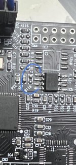
1) I'm not sure if the EEPROM supplied onboard was SPI or I2C because I can not find datasheets for it. However I do know my board was set to use an I2C EEPROM because of the ressitors in use around the EEPROM.
So, I replaced the EEPROM IC with a known I2C device (512bytes).
2) The ADAU1452 datasheet P.52 specifies that it looks for self-boot EEPROM on address 0x50 (7-bit hex). In Sigma Studio on the USBi controls (8-bit) this is 0xA0.
This means on most I2C EEPROMs (incl. the one I used), all 3 of the address pins must be pulled low (grounded). However the PCB in factory configuration had EEPROM Pin 1 connected to ADAU1452 pin 26 'SS_M/MP0' and when running this pin is HIGH 3.3V. This means the EEPROM address is not 0x50/0xA0.
3) The ADAU1452 datasheet P.52 specifies that Pin 26 'SS_M/MP0' must be pulled LOW to define EEPROM as I2C. (Pin 26 HIGH = SPI).
Since ADAU1452 pin 26 is connected to EEPROM Pin 1 I simply pulled EEPROM Pin 1 LOW to ground.
Now it works!
I can program the EEPROM by right clicking the ADAU1452 in the SigmaStudio 'hardware' tab and choosing SelfBoot Memeory > Write latest compilation through DSP. It doesn't seem to matter if the self boot pin is enabled or not.
However, I did also find that I can write the I2C EEPROM a second way:
Connect programmer board directly to EEPROM pins SCL and SDA. In the hardware tab you can Right-click on the EEPROM IC2 > Read/Write Window. Follow the images below to write directly to the EEPROM from the programmer board. The IC2 .hex file will not be generated unless you already clicked 'Link, Compile, Upload'.
This method actually writes faster than doing it through the DSP, but of course you need to connect the programmer directly to the EEPROM.


Attachments
Could someone provide the DSP board (alone) PCB dimensions? I haven’t seen it listed in any of the ads and would like to do a preliminary layout before my board arrives.
All the current ads for the DSP boards (Aliexpress, Ebay) have the STM32F103C8T6 uC included. I plan on using just the DSP board alone and wonder what the uC does and how it will impact/limit what I can do in my SigmaStudio project. Thanks….
All the current ads for the DSP boards (Aliexpress, Ebay) have the STM32F103C8T6 uC included. I plan on using just the DSP board alone and wonder what the uC does and how it will impact/limit what I can do in my SigmaStudio project. Thanks….
I'm traveling and don't have the board with me. But I can answer the STM32 question: unless you program the STM32 using its SWD port and a proper development chain for the STM32, it's like the STM32 doesn't exist. From a SigmaStudio point of view, the STM32 is not there.All the current ads for the DSP boards (Aliexpress, Ebay) have the STM32F103C8T6 uC included. I plan on using just the DSP board alone and wonder what the uC does and how it will impact/limit what I can do in my SigmaStudio project. Thanks….
Using the STM32 would allow you to reprogram the DSP on the fly, respond to external events, etc. But if you don't program it, it will just sit there doing nothing. It comes from the factory unprogrammed, so nothing to worry about

So, in other words, there's zero point of me buying a board with the STM32.
I was considering it since mine came without it.
I was considering it since mine came without it.
Well, it all depends on your interest in programming the STM32. It's pretty easy to do (can even use the Arduino framework), and a very powerful processor family. Having the choice to buy a DSP board without STM32 or one with the STM32 for a little bit more, I'd go with the one with the STM32, just in case. But if you already have a DSP board without the STM32 and don't need the additional functionality, then you might as well wait to buy a new board when you need it: by that time, there might be better boards.So, in other words, there's zero point of me buying a board with the STM32.
The STM32 would allow you to change the DSP parameters on the fly, add screens, input devices, etc. But as a pure fixed function DSP, the STM32 does not add anything.
I know it's been a while since I was very active, but I can't figure out how to quote the latest post lol!
No, I don't need it for anything at the moment and I already have the board without the STM32.
Arguing enough with an STM32 version on my 3D printer's controllerboard(SKR Mini E3 V2.0) in VisualStudio🙈
No, I don't need it for anything at the moment and I already have the board without the STM32.
Arguing enough with an STM32 version on my 3D printer's controllerboard(SKR Mini E3 V2.0) in VisualStudio🙈
Highlight the text you wish to quote and a small 'quote' tab will appear next to the highlighted text.I know it's been a while since I was very active, but I can't figure out how to quote the latest post lol!
Thank you 🙂Highlight the text you wish to quote and a small 'quote' tab will appear next to the highlighted text.
Greetings -- I have the same dsp/codec combo as this other user did (adau1452 and cs42448), and have been pulling my hair out for days trying to get it to work at all, and I can find no concrete config documentation or working project. Either it is defective, or, I am missing something. Is it at all possible for you to re-share the same working base project you shared earlier? Your old link has expired. ceraius@yahoo.comI need your email for wetransfer
Any feedback on the performance of the Aliexpress's ADAU1452 + ADAU or CS CODEC???
It would be great if someone has a good audio interface or an Audio Precision (maybe send it to Erin or Amir) to measure the performance of the implementation of the DSP + CODEC.
It would be great if someone has a good audio interface or an Audio Precision (maybe send it to Erin or Amir) to measure the performance of the implementation of the DSP + CODEC.
@mga2009 I have no measurement equipment, but have been actively programming and testing my ADAU1452+CS42448 for the last few days. I'm doing my listening with a nice pair of studio headphones, and have been happy with the sound so far. No audible background hiss or distortion that I can detect (though, to be fair, I've mid-40s aged ears, so YMMV). Maybe somebody with 'golden ears' will disagree with my assessment, but personally I'm impressed, especially given the price point of these boards.
@Trayal
Good to hear your opinion.
I have the ADAU1452 with the AD 1938 CODEC and also think it sound quite good, subjectively... It also have a TON of options and for the price it's really good... but it would be great to check it's objetive performance, specially the ADC. Hope someone chimes in and provides the proper measurements.
Any chance you share the goods? Thanks in advance!Update: I have received the base project package. Thanks!
Got it from julbo ealier post:
https://www.diyaudio.com/community/threads/low-cost-adau1452-china-board.309680/post-7125948
Thanks!
https://www.diyaudio.com/community/threads/low-cost-adau1452-china-board.309680/post-7125948
Thanks!
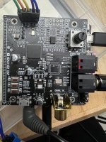
I received this ADAU1452 with daughter board
https://de.aliexpress.com/item/1005...t_main.11.3b695c5f5sx6LG&gatewayAdapt=glo2deu
The "stm32f103" Chip is not fitted
I got all the docs ( china language ) and SigmaStudio files. The board shows LED's , and SigmaStudio download shows success, but I can't get the board to work. No Audio, no readbacks in SigmaStudio.
Made some progress on the ADAU1452+AD1938 board. It wasn't easy. If you got one and are very frustrated, you are not alone.
I got a couple of Dayton 1701 boards plus their output daughter boards, and they are a LOT easier to deal with. However, I wasn't very happy with them as I needed them to do a 2IN-4OUT configuration, and after a lot of painful trial and error, I found out the best way (for me) to get a 4 out of these boards is to use 2 of them so I got each do a 1IN- 2OUT. Wasteful, and a mess of cables.
So I got one of these. ADAU1452+AD1938 board and I went from a high level of frustration to an entirely new higher level in no time.
First, I made the mistake of buying one without the USBi interface. Three more weeks of waiting for that to come in from China.
Once the USBi arrived, the fun began.
I'm not a programmer or an engineer, but I think the STM32 is what gets in the way of making this as easy to program as the Dayton/Wonwom one.
The sparse documentation does not help.
But I got this board to work in a 2 IN - 8 OUT configuration consistently. Nothing fancy, but man, I was just about to trash the darn thing moments before I finally heard a sound coming out of it.
So here is what you need to know.
First, the correct procedure to program it from Sigma Studio is as follows:
(this is with the SPI interface. IC did not work for me)
1 Connect the USBi using the SPI connection
2 Power on the unit with the SIP1 jumper set to 1-2
3 From your SIgma Project, press F7 to link/download to test your config
4 If everything checks out, from the Hardware Configuration page, do a "Self Boot Memory > Erase Memory through DSP
(you only need the step above at the beginning to erase the built-in config))
5 If everything checks out from the Hardware Configuration page, now do a "Self Boot Memory > Write Latest Compilation through DSP
6 Power off the unit
7 Power on the unit with the SIP1 jumper set to 2-3
Following the steps above (without the optional step 4), I have been able to consistently configure the board so I could do <sarcasm on> the incredibly sophisticated test to check which input and output correspond to the Sigma input-output <sarcasm off>
Yeah, because the brutal truth of why many people are struggling to get sound off the board is that the inputs and outputs do not correspond to what would be expected, like input one in Sigma Studio corresponding to input one on the board.
On my board, the connection works as follows:
The Board inputs 0 and 1 correspond to 5 and 6 in Sigma Studio,
The Board inputs 5 and 5 correspond to 0 and 1 in Sigma Studio,
What about 3 and 4? I don't know. I don't care. It is messed up. I need 2 in, and I got them, so for me, this is a win.
And what about the outputs? My heart sank when I realized I had to test each to determine which one goes to which.
This is what I got:
Sigma Out # - Board Out #
0 - Jack 3 R
1 - Jack 3 L
2 - Jack 4 R
3 - Jack 4 L
4 - Jack 1 R
5 - Jack 1 L
6 - Jack 2 R
7 - Jack 2 L
It makes total sense, doesn't it?
Here is what my 4 IN - * OUT config works out. Do not ask me what these RegRead and ReadBack do: I have no idea.
I found on the internet a Sigma Studio template that worked for me, and I ain't gonna fix what's not broken, so...
If you know what they do, I'd like to know too. Hehe.
I attached the template projects: use them with extreme caution.
Attachments
- Home
- Source & Line
- Digital Line Level
- low cost ADAU1452 China board...