The On Semiconductor datasheet for 2SC6043 gives an fT figure for Ic of 10 m.A. with Vce equal to 2 V.
This device is one graphed in an attachment to post 15 on page 2.
How many of the others in the "sub universe" selection have datasheets with this sort of detail.
Agreed that many transistor datasheets are inadequate when shopping for transistors for a new project.
The 2SC6043 shows as obsolete on Mouser.
The On Semiconductor datasheet for 2SC6043 gives an fT figure for Ic of 10 m.A. with Vce equal to 2 V.
This device is one graphed in an attachment to post 15 on page 2.
How many of the others in the "sub universe" selection have datasheets with this sort of detail.
The key here is that it is only a 50V device, and its Ccb at 9 pf seems mediocre.
Cheers,
Bob
The key here is that it is only a 50V device, and its Ccb at 9 pf seems mediocre.
Cheers,
Bob
I like to look at plotting load line graphs to avoid setting Q points too high.The graphs attached to various helpful posts can be put to good use elsewhere.
The main point I was trying to make is the datasheet for 2SC6043 is one of the rare ones that shows graphs of the sort shown in the attachments to post 15 on page 2. I chose this as an example it was the first one suitable for that purpose I happened to see.
By coincidence this datasheet covered the fT issue raised by Scott Wurcer.
After reading this I downloaded the datasheet for ZTX851 the apparent exemplar in this field seeing. On this point the datasheet was silent and I thought in probability others would find see such gaps in other datasheets.
That is an open question. In terms of output capacitance the ZTX851 figure is 5 times greater than that given for 2SC6043.
Attachments
All the ZTX transistors i mentioned previously are made for SMPS, they have quite good slew rates around 100khz square wave , but they are usually driven by transformers.I've seen them in very high voltage power supplies up to 300kv/65 kw driving the output IGBT directly or through transformers.
N101- Quasi saturation term has been around for at least 30 years, though it might have been described as base push-out I guess. As Bob pointed out the Kirk effect is different but related.
It may not have been so commonly understood as that as it took a while for device simulation tools to catch up. AFAIK the first simulator to include this was when Colin McAndrew published his VBIC model which I think was in 1995.
What other terms have you heard to describe quasi-saturation?
john_ellis,
semiconductors suffer terribly from saturation, not from quasi saturation but from real saturation, conventionally called spin saturation or velocity saturation. Quasi saturation appears to be just a deceptive mathematical concoction not anchored in physical theory. You can`t measure saturation or the Early voltage neither experimentally nor mathematically, but you can easily generate nonsensical numbers and graphs programmatically - as a source of amusement.
The Early effect (base width modulation) elucidates the relationship between the collector-base capacitance, input capacitance, transconductance and bandwidth. The Early effect and saturation ought to be kept conceptually distinct.
john_ellis,
semiconductors suffer terribly from saturation, not from quasi saturation but from real saturation, conventionally called spin saturation or velocity saturation. Quasi saturation appears to be just a deceptive mathematical concoction not anchored in physical theory. You can`t measure saturation or the Early voltage neither experimentally nor mathematically, but you can easily generate nonsensical numbers and graphs programmatically - as a source of amusement.
Why do you pollute these threads with this nonsense?
We don't have to agree. What do you dislike and why?
All of the above, quasi-sat is a real phenomena and when modeled produces results that correlate very well to real silicon. If you are a semiconductor physicist with a fully developed alternative description please present it.
What is the difference between quasi saturation and the conventionally understood saturation?
The literature is fertile, I suggest you read it. Quasi-Sat models on several platforms are free downloads.
Are we not trying to push "signal transistors" into power application? A 600mW transistor is too small for the VAS in an amp with more than 40V rail-rail, unless you run it at a tiny current, where their quasi-sat curves are not that bad. The diff-amp also should not be more than a couple mA. Higher power amps need a VAS in a 10W package like to-126, where you will find things like mje340 and mje243. Some of these are a bit slow but we usually saddle them with external compensation caps anyway. So, something to be aware of, but not a real problem.
Just a simple question:
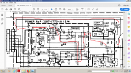
You have here a transistor in class a driving a final transistor in class b forming together an atypical Sziklay pair, it can't be actually named a Szyklay pair at all...
Apart from its merits in controlling crossover distortion in class b ,
is this a form of controlling the final transistors quasisaturation too with the help of the emitor and collector resistors?
Attachments
Are we not trying to push "signal transistors" into power application? A 600mW transistor is too small for the VAS in an amp with more than 40V rail-rail, unless you run it at a tiny current, where their quasi-sat curves are not that bad. The diff-amp also should not be more than a couple mA. Higher power amps need a VAS in a 10W package like to-126, where you will find things like mje340 and mje243. Some of these are a bit slow but we usually saddle them with external compensation caps anyway. So, something to be aware of, but not a real problem.
If a cascode is used, a small signal transistor with beta of several hundred can be the gain device and it can be operated at 10mA while a medium power transistor can see most of the voltage.
I am working on characterizing small signal devices for maximum linearity at minimum voltage at 10mA bias for both input stage and VAS.
Be sure to read the sections of Bob Cordell's book which describe how to get another, somewhat higher voltage, supply rail for the low power sections of a high power amplifier. Now you can cascode to your heart's content without compromising the final output voltage swing.
It's pretty obvious: wind another few turns on the power toroid and put that in series with the main supply. Voila, another 5V or 10V or 15V, whatever you want. Filter it, regulate it, smoothen it, do whatever you like, and apply this to the IPS and the VAS. The extra supply means you can cascode freely. If your amp has bipolar supplies (+V and -V), do this twice.
It's pretty obvious: wind another few turns on the power toroid and put that in series with the main supply. Voila, another 5V or 10V or 15V, whatever you want. Filter it, regulate it, smoothen it, do whatever you like, and apply this to the IPS and the VAS. The extra supply means you can cascode freely. If your amp has bipolar supplies (+V and -V), do this twice.
Do you mean a, b or c?Be sure to read the sections of Bob Cordell's book which describe how to get another, somewhat higher voltage, supply rail for the low power sections of a high power amplifier. Now you can cascode to your heart's content without compromising the final output voltage swing.
It's pretty obvious: wind another few turns on the power toroid and put that in series with the main supply. Voila, another 5V or 10V or 15V, whatever you want. Filter it, regulate it, smoothen it, do whatever you like, and apply this to the IPS and the VAS. The extra supply means you can cascode freely. If your amp has bipolar supplies (+V and -V), do this twice.
Attachments
If a cascode is used, a small signal transistor with beta of several hundred can be the gain device and it can be operated at 10mA while a medium power transistor can see most of the voltage.
I am working on characterizing small signal devices for maximum linearity at minimum voltage at 10mA bias for both input stage and VAS.
A cascode eats up a couple of volts keeping the high gain tranny biased. Quasi sat meany you just lose a couple of volts of undistorted voltage swing. Either way you lose a little output. Ok on 50 volt rails but maybe not on 10. You just need the right transistor - one that keeps all its beta at one or two volts. That’s why you were supposed to buy up a bunch of those C6043’s and the PNPs when they announced EOL.
I'm using ON Semi 50A02CH/50C02CH for upper tranny in cascode arrangement. Its specs look pretty good. Cob is only 2.5 to 3.8pF and no sign of quasi saturation.
In your opinion which of the two transistors in a cascode circuit, benefits the most from low Cbc ("Cob")? The one nearest the supply rail, or the one nearest the output node?
For a given Cob, the cascode is bothered less by it than a regular CE stage. The input stage has low voltage gain, therefore no Miller multiplication. The upper one the base is grounded so no multiplication. The upper one still benefits from low Cob because it still has a high voltage swing, which produces a changing Cob with Vce ( producing high frequency distortion).
- Home
- Amplifiers
- Solid State
- Looking for a small signal NPN with no Quasi Saturation: MEASURED DATA