Thanks guys, appreciate the input.
I have a pair of Hammond 300BXs with 400-0-400 secondaries and looking for about 400VDC, 200mA out of the reg. What sort of value choke should I consider? 5H would be good for chassis space available, those 10H are big buggers! Also, is there an easy rule of thumb or equation to work out component values to determine output voltage?
Sorry again for the dumb questions...
Thanks,
Chris
Not at all Chris. Do you know Duncan Amps' PSU Designer? It's located here: http://www.duncanamps.com/psud2/index.html Just toy around with it, works great.
Yes, I have that. What am I looking for? Max of about 2V ripple? What kind of voltage is the regulator able to drop? I am guessing that you are limited by dissipation, which would be a function of voltage dropped and current passed?
Hope my secondary voltage of 400-0-400 is not too great to get the 400VDC... Cap input would give about 500 to 540 VDC, and a choke input around 340 (with tube rectifier). I think that from memory about 5uF input on the Pi filter gave around 400 volts.....
Cheers,
Chris
Hope my secondary voltage of 400-0-400 is not too great to get the 400VDC... Cap input would give about 500 to 540 VDC, and a choke input around 340 (with tube rectifier). I think that from memory about 5uF input on the Pi filter gave around 400 volts.....
Cheers,
Chris
It all depends on the properties of the regulator. What they all have in common is a buffer for mains variation of +15 to -15% (or more for better regs). So, for 400Vdc out it needs 460V plus some 20-30V drop in the regulator. 490V input to the regulator with 2V ripple would be fine for 400Vdc output.chrish said:What am I looking for? Max of about 2V ripple? What kind of voltage is the regulator able to drop? I am guessing that you are limited by dissipation, which would be a function of voltage dropped and current passed?
radianceaudio said:I got, for the Maida, about 20 milliohms. That was at 365 Vreg, 100 mA DC load, 20 mA sine load at 1 KHz.
As I remember, the Swenson measured out somewhere in the 100 milliohm range.
I think your wrong here - the Swenson reg gives 0.099ohm or lets round it up and say 0.1ohm i.e about 200 times better than the Maida!
As you say good for audio, don't know about guitar amp use?
jkeny said:quote:
Originally posted by radianceaudio
I got, for the Maida, about 20 milliohms. That was at 365 Vreg, 100 mA DC load, 20 mA sine load at 1 KHz.
As I remember, the Swenson measured out somewhere in the 100 milliohm range.
I think your wrong here - the Swenson reg gives 0.099ohm or lets round it up and say 0.1ohm i.e about 200 times better than the Maida!
As you say good for audio, don't know about guitar amp use?
Umm... I may have got the wrong end of the stick here, but isn't 100 milliohms the same as 0.1 ohm? 🙂
jkeny said:Yup, you're right - moral of this is - don't post first thing in the morning, doh!
No worries - I hate Monday mornings as well!! 😀
PSUDII gives me 337V...?Looks like a 50mA load gives 347Vdc with a 550mV ripple before the regulator. Which parts are needed to achieve 325Vdc output voltage instead of 300V? Can it sustain a load of 80mA at 325V?
Output voltage is set by the voltage divider under the LM317, very straightforward! But I haven't built it yet... 😉
OK, maybe I got the Rdc of the secundary a little low 😀Originally posted by Stixx PSUDII gives me 337V...?
Output voltage is set by the voltage divider under the LM317, very straightforward! But I haven't built it yet... 😉
In the past I had this regulator build from M Jones' book but there was quite some heat building up when I pushed the output over 300V @80mA. Hoped you had experience with it 😉
Actually, the output impedance of the Maida, after my mods to it last night, is even lower. It calculates to about 4 milliohms, as opposed to the Swenson at 100 milliohms.
Having said that, I would of course add the caveats:
1. It's a simulation with LTspice; I think it's reasonably accurate, but the real-life application, which I'm working on now, will tell the tale.
2. The difference between 4 milliohms and 100 milliohms is inconsequential; either regulator should work fine, and the Swenson is easier to protect against short circuit. Personally, I would use a much heavier-current-capable mosfet for Q2, without a plastic case, and heat-sink it with a fan-cooled-heat-sink, but everyone has their personal preferences.😉
3. I haven't incorporated the short-circuit protection into the Maida yet, but working on it. My circuit, as it is now, will most assuredly blow up the lm317 in a dead short.😀
4. Both the Maida and the Swenson require some sort of soft start - tube rectifier with RC or CRC or RCRC, etc., or 20K resistor to the center-tap, shorted by a relay of mosfet after a delay. And, for tube amps, of course, both need a delayed B+1 if using SS rectifiers.
Note to Chrish: for a first amp, keep it simple, and don't kill yourself. I'd use Duncan, go CLC or LC depending on your transformer and desired B+1 (my own peculiar designation for the positive voltage applied to the output stage, after filtering...🙄 ), and go easy on the H; most designers, I think, when using a CLC or LC filter, prefer a touch of ripple to slowing down the music (musical transients, that is) too much. Other members here can better give you advice on how much ripple might be tolerable; a lot depends on whether your amp is Single Ended or Push-Pull; in Push-Pull, you can have a lot of ripple on B+1 and not hear it by balancing the ripple across both halves of each Push-Pull output pair, thus zeroing out the ripple. This is what they did in the old days; the old Heathkit AA-151 is a prime example - that amp in the original has the rectified output of the tube rectifier 5AR4 going directly to a 50uF capacitor AND directly to the center-tap of the output transformer; ripple is horrendous, but by using a balancing pot, most of it can be eliminated (not a good design, don't get me wrong, but just an example). If you want to add a Maida later, I'll be happy to dimension it for you, but it's not an easy build for a first amp.🙁 Having come very close to killing myself in the first year that I started messing about with tube amps again, uh...more than once, after a hiatus of forty years, it's so easy to make mistakes, lemme tell you.
Best, Charlie
Attachments
In the past I had this regulator build from M Jones' book but there was quite some heat building up when I pushed the output over 300V @80mA. Hoped you had experience with it
It's all a matter of proper heatsinking...😀
My first regulator was a DC heater supply for my Aikido headphone amp that was initially scaring the s... out of me (having no prior experience) since it was constantly trying to toast parts and my workbench
It has to supply 2800mA at a little over 6V, and man, does it generate heat! I got very good advice from Kevinkr, and though it's quite a bulky unit now it performs flawlessly...Hi all, thought I would through some info in the fray.
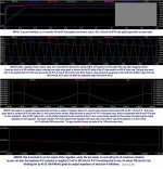
In the bench testing I've been doing the regulator has been pushed into current limit regularly. The basic test voltages are 200V in, 100V out. With the values in the schematic the current limit kicks in at about 500ma. By increasing the current through R3 you can set the current limit set point higher. Keep in mind that as you increase the output voltage the value of R3 needs to be increased to keep the same current limit.
The Swenson regulator does not need a soft start circuit on the unregulated input to function and the regulator provides soft start for components attached to the output.
The low voltage version can handle up to 500V at start up and the high voltage version can handle 900V with the FQAF11N90 MOSFET in the Q2 position, could handle 1000V with a 1000V MOSFET in the Q2 location.
The high voltage version was tested with 625 volts in, 400 volts out. The unregulated supply used for testing has SS rectification so the unregulated supply comes up very fast (lights in room flicker when started).
900V, 11A, 120W not enough? 😉 If the 120W Pd is not enough you can use the metal tab package and bump the Pd up to 300W. Unless you need the Pd, the plastic cases are much easier to use, especially when running high voltages.
Question, does the Maida circuit improve the ripple regulation of the LM317? Looking at the 317 data sheets shows that they max out at ~80dB rejection at 120Hz. The Swensen measures close to 120dB at 120Hz.
When I get some free time I'll build up a Maida regulator and a TL783 regulator and run them through the same tests that the Swenson has been through. Should be some good data generated.
In the bench testing I've been doing the regulator has been pushed into current limit regularly. The basic test voltages are 200V in, 100V out. With the values in the schematic the current limit kicks in at about 500ma. By increasing the current through R3 you can set the current limit set point higher. Keep in mind that as you increase the output voltage the value of R3 needs to be increased to keep the same current limit.
Originally posted by radianceaudio
4. Both the Maida and the Swenson require some sort of soft start - tube rectifier with RC or CRC or RCRC, etc., or 20K resistor to the center-tap, shorted by a relay of mosfet after a delay. And, for tube amps, of course, both need a delayed B+1 if using SS rectifiers.
The Swenson regulator does not need a soft start circuit on the unregulated input to function and the regulator provides soft start for components attached to the output.
The low voltage version can handle up to 500V at start up and the high voltage version can handle 900V with the FQAF11N90 MOSFET in the Q2 position, could handle 1000V with a 1000V MOSFET in the Q2 location.
The high voltage version was tested with 625 volts in, 400 volts out. The unregulated supply used for testing has SS rectification so the unregulated supply comes up very fast (lights in room flicker when started).
Originally posted by radianceaudio
Personally, I would use a much heavier-current-capable mosfet for Q2, without a plastic case, and heat-sink it with a fan-cooled-heat-sink, but everyone has their personal preferences.
900V, 11A, 120W not enough? 😉 If the 120W Pd is not enough you can use the metal tab package and bump the Pd up to 300W. Unless you need the Pd, the plastic cases are much easier to use, especially when running high voltages.
Question, does the Maida circuit improve the ripple regulation of the LM317? Looking at the 317 data sheets shows that they max out at ~80dB rejection at 120Hz. The Swensen measures close to 120dB at 120Hz.
When I get some free time I'll build up a Maida regulator and a TL783 regulator and run them through the same tests that the Swenson has been through. Should be some good data generated.
Well, low voltage high current does not scare me because I wind my own torroids to need so there's not much waisted in the regulation process. Looking at the former HT example there's 90V waisted from the 490Vdc @200mA = 18W/channel = a lot of heat to dissipate 😀Stixx said:It's all a matter of proper heatsinking...😀
My first regulator was a DC heater supply for my Aikido headphone amp that was initially scaring the s... out of me (having no prior experience) since it was constantly trying to toast parts and my workbench
It would be nice if someone could come up with a servo solution; an active combination of series and shunt regulation so the power is given when it is asked for. Hoped Jan D would aswer my question but unfortunately he's wise enough to keep us waiting for the next issue of AudioXpress...
Hello Gary, nice to meet you. Enjoyed your efforts very much. Talking about the new Swenson regulator a couple of us wondered how to obtain a double sided PCB. Can you perhaps produce a graphic output file (GIF or PNG) of the layout so we can produce our own PCB?
Hi Jaap,
Have you tried ordering boards from ExpressPCB?
ExpressPCB operates world wide and lists Netherlands in the "compute board cost" function in their software.
The board file on my web page is formatted to fit on what ExpressPCB calls a "MiniBoard". For the cost of a MiniBoard order you would 3 boards that each contain 2 regulator boards. I cut the boards apart with a large pair of hand shears.
Have you tried ordering boards from ExpressPCB?
ExpressPCB operates world wide and lists Netherlands in the "compute board cost" function in their software.
An externally hosted image should be here but it was not working when we last tested it.
The board file on my web page is formatted to fit on what ExpressPCB calls a "MiniBoard". For the cost of a MiniBoard order you would 3 boards that each contain 2 regulator boards. I cut the boards apart with a large pair of hand shears.
Hi Gary P,
Great to see you here!
I just ran the PCBExpress Compute Board cost for your latest version - $114 for 2 boards shipped to Netherlands (equivalent of 6 regulator boards if 3 per board?)
Order Setup $55
Board setup $2
Board Area 19 sq inches $12.35
Shipping $45
I've attached a single sided version of the board in PCBExpress file (zipped) - maybe somebody can use it to do a single sided board?
Edit: Looking forward to your comparison of the Maida regulator!
Attachments
Hi Jkeny,
You must have done a different order quote. The MiniBoard has a fixed cost for 3 boards that are 2.5"x3.8" and does not have the setup fees and per square inch charge. The MiniBoards are 2 layer boards with plated through holes, no silkscreen or solder mask.
From the compute board cost choose 2 layer, then choose MiniBoard.
Sorry Gary,
Didn't see that option - now $96 delivered price to netherlands
Board setup $51
Shipping $45
So that works out at ~$9 per regulator board + shipping
Didn't see that option - now $96 delivered price to netherlands
Board setup $51
Shipping $45
So that works out at ~$9 per regulator board + shipping
Hi Gary,
Thanks for your post.
Also, thanks for the method of calculating output impedance; very helpful.
When you build up the Maida, there are two ways to do it: stock - with a current limiting resistor, or not attempting (on the first iteration) to provide short protection...I went for the latter for the purpose of lowering output impedance as low as possible.
I'll post a schematic later.
The other thing I did was take a tip from the original National writeup and added 3 x 6.2 zeners between the adjust pin and the voltage divider; this greatly increases the loop gain of the lm317. Low-temp-co Vref IC's would be better, but I'm not concerned about a little Vreg drift with temp for my particular application. When I redimensioned with the 3 zeners in place, output ripple and output variation due to load both went through the floor.
I am impressed that the Swenson doesn't need soft-start for the tx/rectifier side. Perhaps I'm worrying needlessly about the mosfet in the Maida, but Naz's cautionary experiences made me want to play it safe.
Perhaps the Maida with two 1,000 volt mosfets cascaded might make it immune to startup spikes from the tx/rect......
Best, Charlie
- Status
- Not open for further replies.
- Home
- Amplifiers
- Tubes / Valves
- Look for high-voltage regulator projects