HP400 HV tube regulated power supply
Hi guys,
I have built a 280Vdc regulated power supply according to HP400's design. I added a 2H choke before the regulator tube (6BX7 instead of 12B4).
I used it for my clone Marantz 7C line amp and the result is excellent.
This is one I highly recommend.
http://www.mcmlv.org/Archive/TestEquipment/HP400.pdf
Johnny
senderj said:Giaime, jackinnj,
Thanks for sharing your schematics. I would like to know how to mod the schematics for 220-230 VAC mains? Please advise.
No mods necessary for any of the designs shown. All designs permitted to be shown on the site must have a mains isolation transformer. Just chose your transformer to have the appropriate output voltage with a 220-230 AC input. The regulator never "sees" the line voltage, only the output from the mains secondary.
Sheldon
Re: HP400 HV tube regulated power supply
between V8 and V9, there is another tube without a label. Is this the other half of the 12B4 (or in your case it's 6BX7).
what parts needs to be change so tha I can get "custom" Vout?
do you know the current range it can output?
Thank you.
kmtang said:Hi guys,
I have built a 280Vdc regulated power supply according to HP400's design. I added a 2H choke before the regulator tube (6BX7 instead of 12B4).
I used it for my clone Marantz 7C line amp and the result is excellent.
This is one I highly recommend.
http://www.mcmlv.org/Archive/TestEquipment/HP400.pdf
Johnny
between V8 and V9, there is another tube without a label. Is this the other half of the 12B4 (or in your case it's 6BX7).
what parts needs to be change so tha I can get "custom" Vout?
do you know the current range it can output?
Thank you.
HP400
Hi,
The tube between U8 and U9 is part of U8. The 6U8 consists of a Pentode and Triode.
Put a 100K pot at the output potential divider network. Then, you can adjust the output voltage from 150 to 350Vdc.
The output current could be in range of 35mA when 6BX7 tube is used (with two triodes connected in parallel).
Johnny
Re: HP400
do you mean R61 in the power supply schematic?
thank you.
kmtang said:
Put a 100K pot at the output potential divider network. Then, you can adjust the output voltage from 150 to 350Vdc.
Johnny
do you mean R61 in the power supply schematic?
thank you.
Digging up an'ole thread...
Hi,
Sorry to dig up this thread, but hey: Why start a new one?
I'm currently building an Aikido with JB's faboulous board for the 5687. I add 12au7's as input tubes.
I have this HT psu I made for my linestage, and I'd like to re-use it.
(See the bibster's linestage thread for my first steps into the world of tubes...)
Petit probleme here: The psu, when attached to the aikido board, delivers some 370 V.... just a wee bit too much, innit?!! (This is Question 1)
So I thought I'd better make a regulated PSU (Even though the aikido doesn't quite need hyper-clean B+)
.
And thus I landed in this ole thread.
Did some simming (blame me...) for the proposed Maida reg. and I do have some Q's:
This 1K resistor (R2) blows quite a lot of power, right? 5K version?
and the MJE3439 thinggy as well.. heatsink needed? (Question 2)
Could the Q1 be on the same sink as the 317 (Does it need one? There's like 2 V over it...) (Question 3 and 4)
And while we're there, this MJE3439 doesn't appear in my shoppe's catalog... (Question 5)
Question 6: There's Nooooooooooooooo question 6.
so far, thanks, enjoy your meal, sleep well,
Paul
Salut bibster,
not that I'm an expert....but since I happened to read the same thread with some of the same questions on my mind I might as well answer some of your questions.
Q1. is spec'd as 2W in the original schematic
Q2. I would put it on a heatsink (aren't that expensive after all)
Q3-4. dunno
Q5. alternatives are given in post no.16 by jackinnj
seulement mes 2 eurocents,
Oliver
Danke Stixx,
I need to change glasses.... didn't see jackinnj's post (And I just LOVE his avatar... computer says 'Nooo')
I'll fetch some mje340's and I have some 6C/W sinks laying around...
Regards, Paul
I need to change glasses.... didn't see jackinnj's post (And I just LOVE his avatar... computer says 'Nooo')
I'll fetch some mje340's and I have some 6C/W sinks laying around...
Regards, Paul
This one look's realy nice
http://heffa.ath.cx/heffa/heffa/heffareg.pdf
IIt's a high power regulator with softstart
0-800v and more than 250ma
http://heffa.ath.cx/heffa/heffa/heffareg.pdf
IIt's a high power regulator with softstart
0-800v and more than 250ma
There is an error in the shcematic diagram in the "HEFFA" regulator pointed to in the previous post. The Gate and the Drain leads on the mosfet are reversed. The soft start feature in this design will guarantee that the LM317 will have a short unhappy life in an overload situation. The long time constant at the mosfets gate will cause a slow decay in the mosfets source voltage causing the LM317 to be subjected to more than its rated voltage. Yep I blew up a few.
I have been experimenting with a MegaMaida regulator. The simulations are very good, but it will still blow up if I put a screwdriver across the output while it is running. It will survive a short at turn on. The simulation below shows the output ripple while the load is switching between 100 mA and 200 mA at 420 volts. All of the components on the right of Vout are for simulation purposes and are not part of the regulator.
I have been experimenting with a MegaMaida regulator. The simulations are very good, but it will still blow up if I put a screwdriver across the output while it is running. It will survive a short at turn on. The simulation below shows the output ripple while the load is switching between 100 mA and 200 mA at 420 volts. All of the components on the right of Vout are for simulation purposes and are not part of the regulator.
Attachments
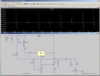
Looks great Tubelab! Are you going to design a PC board for it?. Also, what transformer (voltage/current rating) were you using during these simulations?
This simulation was done using a DC source of 500 volts with a DC resistance of 100 ohms. I ran several simulations at different voltages, currents, source impedances, and load conditions. I also tried several variations of the circuit. All were derived from the Maida design on National web site. This one shows a Linear Technology regulator chip because LT spice doesn't give you models for their competitors chips. The simulations are all buried deep inside my old computer. I just haven't had the time to copy all of it to the new one.
I built a breadboard version on perf board last year. I ran it with a monster Antek toroid that was something like 800 volts center tapped at 1/2 amp. I used a big IR fet (don't remember the #) and a NJR 317 type regulator because it comes in an insulated package. I connected the whole power supply up to a SimpleSE amp and it sounded nice. I didn't have much time for testing, but I did manage to blow the circuit up by shorting it out while it was running.
I had planned to do a PC board, but too many things have gone wrong this year. I did a test board that contained one of these power supplies, a universal PowerDrive circuit, and a few other experiments in December. It has been sitting on my workbench untouched since then. It will be at least 2 more weeks before I can get to work on any electronics. I must finish my taxes, my mom's taxes, the corporate taxes, and the corporate annual reports first.
tubelab.com said:I must finish my taxes, my mom's taxes, the corporate taxes, and the corporate annual reports first.
Well that should take all of 4 hours 🙂
If you have the bode-cad module for LTSpice consider inserting an a.c. source into the error circuit and calculate the impedance plot.
Thought I'd resurrect this old thread as I have a design that some people might be interested in or would like to comment on.
Its actually two choke input PSUs (515v and 415v) with soft start.
I'll explain the topology for those who are frightened:
The transformer on the right has center-tapped outputs of 650v and 550v the higher of these is taken through the LC filter, a shunt regulator to ensure the choke acts properly, the first stage FET regulator/soft start, then splits to two LM1086 regulators (one per channel) giving approx 515V out at 35mA per channel. This supply is for the direct coupled input and driver stages of the amp (Class A LTP 6SN7) and theoretically(!) has minimal ripple. The FETs are STP4NK80Z mounted on a reasonable heatsinks as during startup they pass current while dropping ~550V. The 1086s are trying to produce 515 v so until the FETs are running they drop minimal voltage.
The lower supply from the transformer is again fed though a common LC + shunt regulator but then splits into separate soft start / FET regulators (mounted on LARGE heatsink). These provide acceptable ripple by themselves at 100mA per channel for the 807 LTP output stages.
BTW: The stacked caps might seem a little funny but they are reclaimed from old TVs and stuff.
Any comments appreciated. Is it OTT? Bound to blow up? Amazing piece of ingenuity?😉
Attachments
*wiggles fingers and resurrects thread from grave*
I've got a quick question someone might be able to address about the Maida regulator - there's a resistor of comparatively low-value interposed between the pass device that MJ notes has been kept around for other reasons than Maida's - I'm trying to dimension this resistor and am unsure what sort of power I should expect it to dissipate.
Since it's low value (I think 100 ohms in the canonical application note, 47 in MJ's adaptation), I expect that the answer is "not much", but I expect that if it goes poof, so does much of the rest of the circuit.
That, and other two low-value resistors in the design I assume can be safely exempted from the general "this is probably going to get very hot" rule I apply to most things.
-k
A devices power dissipation can be calculated in many ways, the simplest being:
P=IV
Where P = Power dissipated (Watts)
V = volts dropped accross the device (Volts)
I = Current through the device. (Amps)
However in this case the most practical way may be
P=I²R
Again, P = Power dissipated (W)
I² = The square of the current through the resistor (the supply current + a few mA for the potential divider)
R = Resistance (Ohms)
As you can see, the power dissipated is far more dependant on the current through the device than the resistance so it is always wise to check the dissipation.
Other main power equation is: P = V²/R
Hope this helps
tubelab.com said:I used a big IR fet (don't remember the #) and a NJR 317 type regulator because it comes in an insulated package. I connected the whole power supply up to a SimpleSE amp and it sounded nice. I didn't have much time for testing, but I did manage to blow the circuit up by shorting it out while it was running
I sincerely hope you put a zener diode across source and gate of the MOSFET to protect it from (severe) overvoltage in case of a short (or starting into a large output cap)... that may be the reason it blew up.
@Gaime, your design is also missing this zener, I can pretty much guarantee it will not urvive a short or even starting if a sufficiently large output filter cap is used.
Two points / questions.
1: Aren't most high voltage mosfets integrally zener protected anyway?
2: Why do you guys try to design things that wil survive being shortcircuited? I fully expect any regulator that I build to blow if I put a screwdriver across the output, but I'm not really planning to do that. If I was so kak-handed that this was a regular accident I wouldn't be messing with high voltage suff anyway.
- Status
- Not open for further replies.
- Home
- Amplifiers
- Tubes / Valves
- Look for high-voltage regulator projects