StoneT, I can't open your image of your softstart supply. I'm interested, and up and running with LTspice...a softstart supply is precisely my next step.
I have the capacitance multiplier circuit running in LTspice, modified from Rod Elliot's for high voltage (the transistors aren't quite right but close enough) and the output FFT is fabulous, BUT I haven't solved the voltage differential CEO that develops during initial startup, too much, will blow the transistors😀
Could you repost in a format I can open, or would you like to swap LTspice schematics?
Best, Charlie
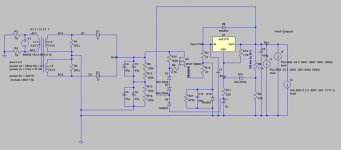
This is my HV power system£¬ It is long time good work¡£
Heat power use LT1084 .
Heat power use LT1084 .
An externally hosted image should be here but it was not working when we last tested it.
sjh327, did you mean to post a file or schematic or photo?
There's just your post, which is encouraging and interesting.
I now have the Maida working great in LTspice with an STP mosfet; on to making it delayed application and softer start.
I'm not so worried about short-circuit protection for now, something for the future.
Best, Charlie
There's just your post, which is encouraging and interesting.
I now have the Maida working great in LTspice with an STP mosfet; on to making it delayed application and softer start.
I'm not so worried about short-circuit protection for now, something for the future.
Best, Charlie
Hi sjh327,
Nice neat layout.
My only concern are the capacitors so close to the heat sinks. How hot is the area where the capacitors are in after running for a couple hours?
-Chris
Nice neat layout.
My only concern are the capacitors so close to the heat sinks. How hot is the area where the capacitors are in after running for a couple hours?
-Chris
Tubelab, et al,
the circuit below, in LTspice, shows current through the lm317 limited to under 800 mA in a dead short, with the voltage across the lm317 very low.
This is just a sim, and I do plan to build it now and screwdriver the output and see wha' happens, but I thought I'd post it.
Yeah, I know, it has small current limit resistors and a whopping cap between the current limit resistors before the lm317 input, which is supposed to be a no-no, but with this I get no sag, and virtually no effect on the B+1 output even with pretty complex and heavy loading, easily twice the loading it will actually see in the amp I'm doing.
Nonetheless, at least according to LTspice, the lm317 doesn't blow. Reality may be different😀
I'll try to attach both the image and the zipped schematic file, if anyone wants to run it or play with it; I tried to put all the files needed inside it.
Best, Chas
Attachments

I'm surprised nobody has linked to John Swenson's High Voltage Regulator which is a mod of Gary Pimm's CCS designs - just look at the graphs to see how good this regulator is - see here: http://www.pacifier.com/~gpimm/regulators.htm
I don't know any regulator which has been analysed as well as this from highly reliable technical perspective. John Swenson has used these extensively & swears to their sonic excellence!
I don't know any regulator which has been analysed as well as this from highly reliable technical perspective. John Swenson has used these extensively & swears to their sonic excellence!
When you look at the graphs for this circuit bear in mind that this was before the final tweaks were discovered (the slight rise in the LF is now flat across the full bandwith) - nevertheless their stunning - output impedance .099ohm at 1KHz - PSRR ~-145dB from 1 to 50KHz. With some change of parts, the ability to deal with voltage > 500V & high currents (heatsink needed). Board size 2.5" by 1.9". John Swenson says this about it (over at AA) http://db.audioasylum.com/cgi/m.mpl?forum=tubediy&n=121573&highlight=john+swenson&r=
I believe this would make a great group buy - the BOM & PCBExpress files are in his sites download area, I just noticed that he added them on 18 Jan. There' just one mistake on the board C5 is connected wrong but he refers to that and shows the correct connection - just can't be accommodated on the existing board layout.
He has put these files on-line to aid the DIY community so no IP/permission issues for non profit use. If anybody wants to do some boards I'm interested in buying 10 at a reasonable price.
I tried a bunch of different designs I could find on the web and non of them were doing all that great until I got to the last group. I tried series regulators and shunt regulators, tube, BJT and MOSFET......The sonic results of this are way better than anything else I've ever tried. The line rejection is quite high and very low output impedance from very low frequencies to well above the audio range......I haven't finished all the experiments yet, but things are leaning towards the conclusion that results from using this regulator are sonically better than what I got with the low DCR, low H C etc design. As far as I could tell what that supply gave me was a quite low output impedance over the whole audio range with very fast recovery for large transients. The regulator design does the same thing, very low output impedance over the whole audio range, and no transient issues at all as long as the supply driving it has the power to handle the largest transients.
I believe this would make a great group buy - the BOM & PCBExpress files are in his sites download area, I just noticed that he added them on 18 Jan. There' just one mistake on the board C5 is connected wrong but he refers to that and shows the correct connection - just can't be accommodated on the existing board layout.
He has put these files on-line to aid the DIY community so no IP/permission issues for non profit use. If anybody wants to do some boards I'm interested in buying 10 at a reasonable price.
Swenson's reg does look impressive, indeed.
I saw the PCB file at Pimm's for PCBexpress.
Are there finished boards available for sale?
And...what are the overall current specs on it? I'm assuming it's certainly good to 600V or higher, but I'm not sure what current it can handle.
Best, Charlie
I saw the PCB file at Pimm's for PCBexpress.
Are there finished boards available for sale?
And...what are the overall current specs on it? I'm assuming it's certainly good to 600V or higher, but I'm not sure what current it can handle.
Best, Charlie
Another question....
Does anyone have any experience with how the Swenson regulator handles sag?
One of the things I like about the Maida...although I can see the Swenson appears to be significantly better...is that it regulates ripple well under sag conditions, making it a candidate for a regulator for a guitar amp with the possibility of adding a variable "sag" control...
Does the Swenson maintain ripple rejection under sag conditions?
Best, Charlie
radianceaudio,
All the info is on his site - I believe the test graphs were run at 100mA. The current is limited by the heat dissipation of the Mosfet device Q2 From the site:
There are no boards available - that's why he supplied PCBExpress files & BOM so DIYers could get boards made!
Now whose interested in doing a GB? These boards should be cheap & all the components are relatively cheap also.
All the info is on his site - I believe the test graphs were run at 100mA. The current is limited by the heat dissipation of the Mosfet device Q2 From the site:
The regulator circuit with current limit is quite robust. I've repeatedly shorted the output to ground and it survives. Just keep in mind the power ratings of the output MOSFET. With 180 volts across Q2 and 300ma the power dissipation during the shorted condition in this test was 54 watts, way over the 33 watt limit.
For high power or high voltage operation the board is setup to take either TO220 or T03P packages for Q2. I highly recommend the fully en capsulated parts for safety. The full encapsulation reduces the power disapation ratings but is made up by the ease of attaching to the heat sink without worry of arc-over and corona issues
There are no boards available - that's why he supplied PCBExpress files & BOM so DIYers could get boards made!
Now whose interested in doing a GB? These boards should be cheap & all the components are relatively cheap also.
What do you mean sag? The voltage across the lower MOSFET needs to be kept at 20 volts or higher for stability and performance issues.
"his site"...do you mean Pimm's site, or is there one for Swenson? I could only find the one page writeup at Pimm's. However, making the PCB file available is very gracious indeed.
Sag only applies to a guitar amp...hopefully!
It's simply the condition set up on purpose where B+ is pulled down by overdriving the output tubes and the power supply having too much resistance to maintain the nominal voltage. In a CLC supply, the only problem with sag is you tend to get a lot of ripple coming through. The Maida has the advantage of maintaining ripple rejection during sag.
This Swenson regulator, maybe it's Swensen, I forget, anyway, the output impedance graphs are very impressive, just curious about it's application in a guitar amp.
But for an audio amp, it looks like the best power supply ever designed.
Best, Charlie
I decided to find compare the Swenson output impedance as calculated by Gary Pimm with my latest version of the Maida.
I used his same method.
I got, for the Maida, about 20 milliohms. That was at 365 Vreg, 100 mA DC load, 20 mA sine load at 1 KHz.
As I remember, the Swenson measured out somewhere in the 100 milliohm range.
Of course, without a tube rectifier, with the Maida a 20K resistor does have to be inserted to give it soft start (shorted by a relay or mosfet at the end of the delay period) and a delay circuit added, and perhaps short protection...
But it certainly measures even better than the Swenson, using the same method. And that, by the way, was with only a .01uF output cap; normally I would use a 100uF cap on the output. And, for what it's worth, probably not very much here, it would be easy to make the Maida into a "variable sag" power supply for a guitar amp, which I plan on doing, just for the fun of it.
So, count me out for PCB's, I like tweaking this circuit better, and I greatly prefer circuits well in the public domain, avoids hassles.
But thanks for the info and link, it's always good to see other approaches.
Best, Charlie
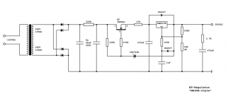
Swenson Regulator
Me too.Originally posted by jkeny
I believe this would make a great group buy - the BOM & PCBExpress files are in his sites download area... He has put these files on-line to aid the DIY community so no IP/permission issues for non profit use. If anybody wants to do some boards I'm interested in buying 10 at a reasonable price.
Excuse the dumb question, but I have only built tube amps with unregulated CRC and CLC input filters. What would one put on the front end of one of these regulators to provide the B+ for a tube amp? Tube rectifier directly to the reg, or is there a Cap, or Cap+choke etc? I am interested in these for my next project...
Thanks,
Chris
Thanks,
Chris
There's no dumb question here 😕 🙂chrish said:Excuse the dumb question, but I have only built tube amps with unregulated CRC and CLC input filters. What would one put on the front end of one of these regulators to provide the B+ for a tube amp? Tube rectifier directly to the reg, or is there a Cap, or Cap+choke etc? I am interested in these for my next project...
Thanks,
Chris
Opposed things are needed in a PS: low impedance vs low ripple. I think it's a good habit to isolate mains interference from the HT by using a tube rectifier. A pi filter made of a choke and a cap is very efficient in reducing ripple. After that the ripple will be at 2Vac most (depending on materials used and power consumption) and can easily be handeled by the regulator.
Some people go the brute force way: sand plus large caps. This gives lower impedance but introduces heavy ringing of the tranny/cap combination, resulting in high frequency noise which has to be cleaned up by the regulator.
My personal believe is to use the regulator for what it is intended to do and to keep out mains noise etc when possible, at the expense of a somewhat higher impedance PS.
Looks like a 50mA load gives 347Vdc with a 550mV ripple before the regulator. Which parts are needed to achieve 325Vdc output voltage instead of 300V? Can it sustain a load of 80mA at 325V?Stixx said:using a Maida regulator as example it could look like this...
(don't hit me when it is not 100%... 😱 )
- Status
- Not open for further replies.
- Home
- Amplifiers
- Tubes / Valves
- Look for high-voltage regulator projects