I just realized the main limitation of the Maida using an LM317...output impedance rises rather badly with increased frequency. Doh!! 🙄
So, while it does achieve less than 10 milliohms at 1 KHz, at 20 KHz the output impedance rises into the many hundreds of milliohms...not good.
I still like the basic topology of the Maida, however, it's just the LM317 portion needs to be replaced with the equivalent of a Jung super regulator...which I'm working on.
Question for Gary P or Mr. Swenson: how much does the output impedance of the Pimm/Swenson HV regulator change from 1 KHz to 20 KHz?
Best, Charlie
Here's the graph from gary's site for this regulator & his comments:
I think he has further improved the impedance curve to reduce the rise at LF - it is now flat from LF to 20KHz AFAIR
Edit: I meant to ask Disco if he got his LND150s & other mosfets yet & has he built the board up yet? Any results?
You can see that the output impedance (Z) of the circuit with current limit (red trace) (.142 ohms output Z) fits between the green trace where the 2 ohm resistor is shorted out (.099 ohms output Z) and the black trace where a .1 ohm resistor is added (~.2 ohms output Z).
.........
Over all, this looks like a darn nice regulator. The output impedance is quite low without using large capacitors and the ripple rejection is suburb.
I think he has further improved the impedance curve to reduce the rise at LF - it is now flat from LF to 20KHz AFAIR
Edit: I meant to ask Disco if he got his LND150s & other mosfets yet & has he built the board up yet? Any results?
Attachments

Well, that was interesting. Keep in mind this is just a simulation, and all I'm doing is reporting, not making any judgements.
I went ahead and modeled the Pimm/Swenson regulator in LTspice, but redimensioned it (only the bottom resistance) for 360 volts out.
I was very surprised that when I put the same load on it that I've been using with the Maida, the SIM results were considerably worse.
Much more ripple and much higher impedance, and at higher frequencies the impedance rose faster than the Maida.
Now, this is just simulation. But the blasted sim did cause me several days of grief, as I worked to lower the output impedance of the Maida at higher frequencies. But it's a lesson to go ahead and build once the fundamental issues are worked out - I don't think spice is for trying to get it to the nth degree - and then take real-world measurements. I suspect the results will be different - as the results for the Pimm/Swenson might well be very different from the sim, and considerably better than the sim predicts.
Anyway, I'm a little more hopeful now for the Maida; we'll see.
Best, Charlie
Thanks. Yeah, that was my point, I guess I wasn't clear enough.
My hope is that since the sim showed the Swenson doing so badly, erroneously since Gary P's real-world measurements were far better, the real-world performance of the tweaked Maida might be considerably better than what the sim showed. I hope. We'll see.
Or LTspice is just good for working out the fundamentals, but doesn't predict reality when you get down to trying to calculate milliohms of output impedance and high frequency noise rejection, etc. Seems I remember Bob Pease saying a few choice words on that subject....😎
I'm reluctant to give up the Maida topology, because it has some features I like, I think it can be made bullet-proof (but not with any sizable cap at the LM317 input!), I also think there's some decent possibilies for replacing the LM317 with a better reg or even a superior discrete circuit, and it's solidly public domain. Whether Gary P really has any intellectual property rights to the Pimm/Swenson, and whether I am obligated to pay him/them a royalty if I use it to upgrade an old amp for profit (well, not really - it's more like slave labor 🙄 ) I don't know, and it makes my head hurt to think about it.
Just to be clear about this, for anybody, I am not interested in a flame war over Gary P's intellectual property rights; I think he and Mr. Swenson are top-notch designers - real engineers, not an old hack like me - and I'm grateful that he's made his work available, and if I had disposable income I would happily buy any PCB's or kits he wished to sell. If I was rich, I'd send him a monthly royalty payment for no reason other than to encourage him to continue his superb work.
So, if I can make the Maida work decently, all to the better, just more meat for the stew.
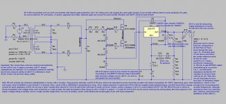
Just for chuckles I attached the latest version of the Maida; it still doesn't have short-circuit protection, but I have found that there are numerous ways to take the mosfet gates to ground (or to other nodes later in the circuit) which protect the LM317 very quickly against both over-voltage and over-current in a short, so I'm optomistic.😀
Just, please, nobody dream up a protection circuit and then post it here with a copyright...that I WILL ignore.
Best, Charlie
My hope is that since the sim showed the Swenson doing so badly, erroneously since Gary P's real-world measurements were far better, the real-world performance of the tweaked Maida might be considerably better than what the sim showed. I hope. We'll see.
Or LTspice is just good for working out the fundamentals, but doesn't predict reality when you get down to trying to calculate milliohms of output impedance and high frequency noise rejection, etc. Seems I remember Bob Pease saying a few choice words on that subject....😎
I'm reluctant to give up the Maida topology, because it has some features I like, I think it can be made bullet-proof (but not with any sizable cap at the LM317 input!), I also think there's some decent possibilies for replacing the LM317 with a better reg or even a superior discrete circuit, and it's solidly public domain. Whether Gary P really has any intellectual property rights to the Pimm/Swenson, and whether I am obligated to pay him/them a royalty if I use it to upgrade an old amp for profit (well, not really - it's more like slave labor 🙄 ) I don't know, and it makes my head hurt to think about it.
Just to be clear about this, for anybody, I am not interested in a flame war over Gary P's intellectual property rights; I think he and Mr. Swenson are top-notch designers - real engineers, not an old hack like me - and I'm grateful that he's made his work available, and if I had disposable income I would happily buy any PCB's or kits he wished to sell. If I was rich, I'd send him a monthly royalty payment for no reason other than to encourage him to continue his superb work.
So, if I can make the Maida work decently, all to the better, just more meat for the stew.
Just for chuckles I attached the latest version of the Maida; it still doesn't have short-circuit protection, but I have found that there are numerous ways to take the mosfet gates to ground (or to other nodes later in the circuit) which protect the LM317 very quickly against both over-voltage and over-current in a short, so I'm optomistic.😀
Just, please, nobody dream up a protection circuit and then post it here with a copyright...that I WILL ignore.
Best, Charlie
Attachments
Hi,jkeny said:I meant to ask Disco if he got his LND150s & other mosfets yet & has he built the board up yet? Any results?
Considering the purposes I use the regulator for, I descided to go back to the original design of J Swenson as posted on Audio Asylum. Re-reading Garys article I came to understand two parts were optimized: the resistor on top of Q5 and the value of the output cap. He also increased the value of the noise cancelling cap on the voltage reference. After that point the circuit was altered because of Garys need for a short circuit proof version and further optimizations were for that circuit only.
Yes, I've received the Mouser order faster than I believed possible 🙂 A first print was made but when I changed some resistors it showed the wires and pads of the PCB were too small and broke off. So I developed another, simpler version for the original SwensonReg exactly to fit the parts I had at hand and it works like a dream.
Right now I'm listening to a small (3W) tube amp which is powered by the new reg. The sonic impact on low frequencies is very good as bass notes sustain without sounding 'hollow' as I was used to. This hints on a very low impedance power supply. For voices and high frequencies I'm not impressed and I suspect the amp is suffering from oscillation. It might be caused by coupling because the PCB and the tube are mounted close together, or because of bad wire layout, or because of the sand I used in the recitication.
The input voltage is 350Vdc (0,3V ripple), current is 30mA, output voltage is 275V. There's no need for a heatsink on Q1, Q2 needs only a small one. Output voltage for this small load is rock steady and is maintained while Vin-Vout > 25 volt. Very good indeed!
Thanks Jaap,
Good information. You are using the attached JS Vreg, then?
Some of Gary's mods (apart from the High voltage & current limiting stuff) improved performance of the reg, as you correctly identified - specifically (referring to the attached schematic) R14 increase, C2 increase & C1 increase.
Some of the indications that GP has said is that the reg works best with a voltage drop of about 100V (certainly >50V) due to the capacitance of the mosfets reducing at higher Vs. This is probably the same advice as JS gives that " for best results you should have at least 20mA flowing at all times"
Not sure if this helps!
Attachments
Hi,
Indeed, that's the circuit. I've raised the output voltage to 275V by increasing the resistance of the voltage reference (R10 and R11 in Garys drawing) to circa 800K and also my load differs from his situation.
Gary writes:
1) Increasing the output cap to 470nF took care of occasional instabilities.
2) Increasing C2 to 10uF increased ripple rejection at 120Hz down to 120dB.
3) Increasing R14 to 56K increases the load on Q5 for higher gain for error correction and it increases the voltage across Q1 improving its operating point.
As some parts I used in the amp were rather old I should give it some time to brake in. But high and mid are not as clean as with this tube regulator Nice bass and dynamics right now 🙂
I believe GP said that at least 50V drop is needed across the Vreg (100dB PSRR) but 100V is better (120DB PSRR)
GP's post on this: http://db.audioasylum.com/cgi/m.mpl?forum=tubediy&n=88436&highlight=gary+pimm+john+swenson&r=
GP's post on this: http://db.audioasylum.com/cgi/m.mpl?forum=tubediy&n=88436&highlight=gary+pimm+john+swenson&r=
Yes, Gary shared knowledge on this matter. 75V drop might just be OK for this situation as I measured flat DC with my FLuke 87. It always gives some mV AC when I hold the terminals in the air 🙂 What might be more interesting is what the effect of the amount of voltage drop is on the bandwith of the regulator.
After a couple of hours listening things improved a little. I'm curious what the impact will be of a choke (maybe a common mode choke?). Furthermore I need to investigate oscillation as per this post.
After a couple of hours listening things improved a little. I'm curious what the impact will be of a choke (maybe a common mode choke?). Furthermore I need to investigate oscillation as per this post.
disco said:
Considering the purposes I use the regulator for, I descided to go back to the original design of J Swenson So I developed another, simpler version for the original SwensonR
Jaap,
I cannot email you. If you might decide to make more PCB's or buy them from PCexpress I would also be interested .
regards,
(the real) Jaap
Some of the indications that GP has said is that the reg works best with a voltage drop of about 100V (certainly >50V) due to the capacitance of the mosfets reducing at higher Vs.
Ah, that explains my results in the sim with a rather smaller voltage drop using the Pimm/Swenson. I suspected the capacitive transfer of the mosfets was the problem.
So, the Maida is actually the better choice, so far I believe, for situations where a much smaller voltage drop is needed, because the LM317 interposes between the capacitive transfer of the voltage-protecting mosfets and the output. The Pimm/Swenson regulator can undoubtedly be optimized for this purpose, I suppose, but I would rather optimize the Maida by replacing the LM317 with discrete components.
In any case, the Maida at 1 KHz now has neglible output impedance, and I'll find out if the rise in high frequency impedance as predicted by the sim makes a difference in real application.
For what it's worth, I did sim up several versions of the Jung super reg as the last stage in the Maida, and for my purposes, moderately high B+ and moderately high current demand, the super reg did not perform as well as the lowly LM317 as the output stage of the Maida; perhaps a super reg topology for the output with discrete components rather than an op amp might perform much better. Another option is a floating "capacitance multiplier" output, but all these options are a bit problematic at high voltage - at least for short circuit protection and possibly excessive voltage differentials during startup - unless they're wrapped into the same loop as the LM317 is.
Best, Charlie
It would be great to get a sonic comparison of the GP/JS Voltage reg versus the Maida - sims have a value up to a certain point.
John Swenson has stated this
Over at this thread http://db.audioasylum.com/cgi/m.mpl...ight=tried+various+regulators+john+swenson&r=
John Swenson has stated this
I tried a bunch of different designs I could find on the web and non of them were doing all that great until I got to the last group. I tried series regulators and shunt regulators, tube, BJT and MOSFET. My previous best result was a shunt regulator driving a series regulator (I got VERY good line rejection from the shunt, but the output impedance was not as low as I liked, the series had very low output impedance, but not so great line rejection). This combo sounded pretty good but was very complicated and needed large heatsinks, it wound up wasting a lot of power.
What changed this was a bunch of threads on regulator design over at diyhifi.org, this got me really analyzing the designs and finding the good and pad parts. I wound up with a modification of the infamous Gary Pimm CCS to turn it into a very nice series high voltage regulator. The sonic results of this are way better than anything else I've ever tried. The line rejection is quite high and very low output impedance from very low frequencies to well above the audio range.
Over at this thread http://db.audioasylum.com/cgi/m.mpl...ight=tried+various+regulators+john+swenson&r=
It IS possible to use a cap input filter with a small cap, say 2-4uf that still keeps the diodes and transformers etc cunducting for a good portion of cycle. I did some experiments with large C, small C and critical inductance choke input and mapping out the junk they spewed into the environment. As has been mentioned the large C sprays a lot of stuff around inside the chasis and into the power cord etc. The choke input gets rid of almost all of that. The small C was almost as good as the choke input. At one point I was trying .47uf, I could not tell any difference with this.
The problem with the small C is a very large ripple after the C. So the transformer voltage has to be high enough that the bottom of the ripple is sufficiently high above the droput voltage of the regulator that you always stay above regulation no matter what the load is. This also means that you are converting that entire portion of ripple above the output voltage to heat, so you need a good size heatsink.
Hi,jkeny said:Yes, I'll be interested in your findings on this - please post when you have some news!
After 24 hours continious burning in the NOS pio coupling cap the course treble improved somewhat. The amp was still far behind to the level it was with the tube reg.
Intuitively I had a closer look to the PS as this part is the worst source of noise. Two small resisters in series with the MR856 diodes improved the hard midrange. Some cables were rerouted and I shielded the input RCA and volume control. By far the biggest improvement came when I exchanged the resister for a 50H choke. Mind you, there's no more than 30mA dissipated from the 47uF - 220ohm - 47uF filter.
Right now I have A) great bass, very tonefull and articulate B) voices sound natural without the former harshness C) high notes on piano and cymbals come to life in a normal manner, one can distinguish nuances D) excellent dynamics, micro details appear out of the sonic 'mist'.
With the Swenson regulator in place the amplifier sounds much bigger than it's humble 3W would expect. This version right now betters the previous equipped with the tube regulator. This calls for further experimentation with the powersupply as its impact on the sonic quality appears massive.
Ok, Jaap,
If I understand you- the Swenson reg is now better than the tube reg it replaced?
The changes you made with adding choke, etc were to the PS in front of the regulator? Can you show where the schematic of your PS?
If I understand you- the Swenson reg is now better than the tube reg it replaced?
The changes you made with adding choke, etc were to the PS in front of the regulator? Can you show where the schematic of your PS?
The powersupply in front of the regulator consists of 280 Vac, full wave rectification with Motorola 856 diodes (no bridge) followed by 22 ohm current limiting resistors, 47uF, 50H choke, 47uF.
Reproduction with the Swenson reg has improved much after I filtered noise from the PS and is now better than previously with the tube reg. It seems the tube reg suffers less from a noisy PS than the semiconductor reg. The tube reg gives a charming laid back character to the music. With the Swenson you get better attack, fast and strong bass notes and more micro details.
Reproduction with the Swenson reg has improved much after I filtered noise from the PS and is now better than previously with the tube reg. It seems the tube reg suffers less from a noisy PS than the semiconductor reg. The tube reg gives a charming laid back character to the music. With the Swenson you get better attack, fast and strong bass notes and more micro details.
I thought/would have imagined that a good voltage regulator is supposed to isolate the PS so that changes in the PS (within reason) have no effect on the clean supply out of the Vreg? Difficult task to achieve, I imagine & it sounds like the changes you made had the effect of reducing the ripple on the raw supply?
From memory Swenson led me to believe that this Vreg was relatively immune to changes in the raw PS - I'll try & dig up the quotes (probably on that thread I already referenced over on AA?)
From memory Swenson led me to believe that this Vreg was relatively immune to changes in the raw PS - I'll try & dig up the quotes (probably on that thread I already referenced over on AA?)
Maintaining a constant voltage is the first goal, low output impedance over a wide frequency range a second and low residual noise the third. High frequency noise is killing for good audio reproduction. The less in, the less comes out.jkeny said:... a good voltage regulator is supposed to isolate the PS
Yes, that too.Difficult task to achieve, I imagine. It sounds like the changes you made had the effect of reducing the ripple on the raw supply?
Ringing of the transformer - diode - capacitor gives very nasty HF noise, hard to filter out once it has entered B+ unless one makes one or more pi filters with a choke and a capacitor. Normally I take a center tapped HT transformer and a rectifier tube to power my amps and use only modest caps in the filter. That way ringing is at a much lower level. It surprised me that with sand @30mA noise was that much noticable.From memory Swenson led me to believe that this Vreg was relatively immune to changes in the raw PS - I'll try & dig up the quotes (probably on that thread I already referenced over on AA?)
- Status
- Not open for further replies.
- Home
- Amplifiers
- Tubes / Valves
- Look for high-voltage regulator projects