It is easier with a source-follower as output stage. A single ended output stage with gain makes it more complicated also to control the distortion.
An interesting amp. When the J2 schematic is official released we will see how much of a clone we have.....
I will probably use 2SK3497 as current source for the output stage so it will not be 100% anyway…….and mono blocks…..and RCA input only. Think I will "strap" it for RCA only on PCB.
An interesting amp. When the J2 schematic is official released we will see how much of a clone we have.....
I will probably use 2SK3497 as current source for the output stage so it will not be 100% anyway…….and mono blocks…..and RCA input only. Think I will "strap" it for RCA only on PCB.
Yep.
(My sim says 1.44, but it's not 100% accurate because I don't have a SPICE model for the 4N35.)
how can we lower or higher bias
how can we lower or higher bias
It's not meant to be changed in the J2.
However, if you'd like to experiment, the bias is controlled by the source resistors. Just keep them in the same ratio (roughly 2:3).
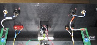
My build is running
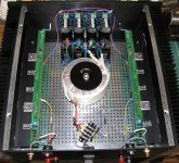
I got my Long and Skinny J2 Clone build working today. My boards are from the recent North America group buy.
I used the 400mm 4U Dissipante chassis and added a horizontal angle to each channel's heatsink.
With a 400VA Antek transformer it runs about 22.1 VDC rails.
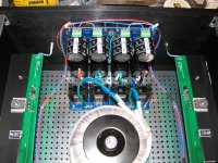
Bias is settling in at about 1.425 Amps. Very easy to establish and hold offset at 0-1 mA.
I used 30 watt Caddock resistors as they can be secured with 3mm machine screws and have adequate lead length to mount as shown.
Using Keratherm pads for the Semisouth Jfets, in my shop with 19 degree Centigrade ambient temps, the Jfets are running about 53 degree C, nearby heatsink is 47 degrees and fins are at about 39 degrees.
So far, so good, I hope to get it into my system this weekend for some listening tests....
Thanks to all involved in getting these boards developed and available to us plebians.
Matt
Matt
I got my Long and Skinny J2 Clone build working today. My boards are from the recent North America group buy.
I used the 400mm 4U Dissipante chassis and added a horizontal angle to each channel's heatsink.
With a 400VA Antek transformer it runs about 22.1 VDC rails.
Bias is settling in at about 1.425 Amps. Very easy to establish and hold offset at 0-1 mA.
I used 30 watt Caddock resistors as they can be secured with 3mm machine screws and have adequate lead length to mount as shown.
Using Keratherm pads for the Semisouth Jfets, in my shop with 19 degree Centigrade ambient temps, the Jfets are running about 53 degree C, nearby heatsink is 47 degrees and fins are at about 39 degrees.
So far, so good, I hope to get it into my system this weekend for some listening tests....
Thanks to all involved in getting these boards developed and available to us plebians.
Matt
Matt
Attachments
thanks, all.
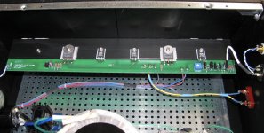
the j109s are all matched to about 9.5mA, the sk170s are matched at 7.6mA.
I am near the end of my matched front end jfets, unfortunately.
the j109s are all matched to about 9.5mA, the sk170s are matched at 7.6mA.
I am near the end of my matched front end jfets, unfortunately.
Great idea on the TO-220 Caddocks, Matt! (Much easier than fiddling around with the little brass bars like I did.)
@Matt
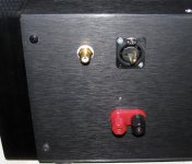
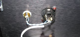
Do me a favor and take a good shot of the RCA+XLR connections, I was thinking of going that route as well....
JT
Do me a favor and take a good shot of the RCA+XLR connections, I was thinking of going that route as well....
JT
@JT
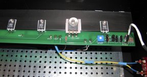
I just do standard wiring per Pass Labs / FirstWatt
RCA signal to pin 2 on xlr
RCA ground to pin 1 / chassis ground on xlr
When using the rca input, I use Cardas CGSP shorting plugs in the xlr from pin 3 (- negative input) to pin 1 (ground).
Matt
I just do standard wiring per Pass Labs / FirstWatt
RCA signal to pin 2 on xlr
RCA ground to pin 1 / chassis ground on xlr
When using the rca input, I use Cardas CGSP shorting plugs in the xlr from pin 3 (- negative input) to pin 1 (ground).
Matt
Attachments
I plan to "hardwire" for RCA only on PCB. I have no balanced pre-amps so why not make it as simple as possible…..
how can we lower or higher bias
It's not meant to be changed in the J2.
However, if you'd like to experiment, the bias is controlled by the source resistors. Just keep them in the same ratio (roughly 2:3).
I read somewhere, if you lowering value ofR4 15K, bias current goes higher.
My freshly rebuilt J2 is warming up at the moment, with stock parts, bias current is 1.45A, offset is under 1mV.
Thanks to Papa and Jeff! 😀
Lowering R4 will increase the bias contribution of the current source, increasing the push-pull flavour a bit and decreasing the singled-ended flavour.I read somewhere, if you lowering value of R4 15K, bias current goes higher.
You can also adjust the flavours by modifying the ratio of the source resistors. If the total resistance stays the same then the bias will be the same.
Conversely, if you adjust the total resistance but leave the ratio the same the bias will change but the flavour will be the same.
Or at least that's my understanding of it.
Sweet!My freshly rebuilt J2 is warming up at the moment, with stock parts, bias current is 1.45A, offset is under 1mV.
Thanks to Papa and Jeff! 😀

Thanks for your clarifying answer, I think I can understand what you say.
It perhaps meant, in this way we can change distortion properties of J2 as well?
It perhaps meant, in this way we can change distortion properties of J2 as well?
@JT
I just do standard wiring per Pass Labs / FirstWatt
RCA signal to pin 2 on xlr
RCA ground to pin 1 / chassis ground on xlr
When using the rca input, I use Cardas CGSP shorting plugs in the xlr from pin 3 (- negative input) to pin 1 (ground).
Matt
Thanks for the photos Matt. 🙂
Thanks for your clarifying answer, I think I can understand what you say.
It perhaps meant, in this way we can change distortion properties of J2 as well?
Yep. See also Nelson's discussion of P2 in the PLH amplifier: http://www.firstwatt.com/pdf/art_plh.pdf.
- Home
- Amplifiers
- Pass Labs
- Long skinny builders thread