It is a very nice chassis. I have only had one problem with it. The recess for the I/R remote sensor is a very tight fit. It is hard to align the sensor, and the harness has to be bent sharply coming out off the sensor. This seems to have caused problem with the remote on my unit. It would double or triple count steps or lock up the remote action. I don't know if it was due to misalignment or the bend in the harness. I currently have the sensor sticking out through a small gap in the top cover with the harness straight, and it works fine. In my copious free time I plan to take the front plate off and put it in the mill to chamfer the back of the hole for the sensor and enlarge the slot of the harness.This thread has been quiet for quite some time! I'm considering an Iron Pre with Muses kit from Frank. There was a good bit of conversation about Modushop making a custom chasis, or at least a face plate for this.. I only saw one example above. Was there any more movement on that or options? Thanks for any updated info!
You can go in from the back with a 90° countersink and turn the straight hole into a conical hole leaving the small hole on the outside of the front plate. I would recommend doing it in a drill press or preferably a mill so you have better depth control. That basically makes a pinhole camera and the alignment is much easier.P.S. I use Frank's solution and I love it. However, I am thinking of widening the front panel hole for the IR receiver because it won't pick up anything at an angle unless you are close to it. My equipment rack is on the left wall about 12 feet away from and at a 90 angle to the listening position, and the very narrow hole doesn't work at that position.
Just something to think about before gluing the receiver in.

Great info.. Thanks Argos! Was your build a the SE or Balanced version? Wondering if there are "Franks Muses" versions of each chassis? Had considered SE initially, but leaning towards balanced now..It is a very nice chassis. I have only had one problem with it. The recess for the I/R remote sensor is a very tight fit. It is hard to align the sensor, and the harness has to be bent sharply coming out off the sensor. This seems to have caused problem with the remote on my unit. It would double or triple count steps or lock up the remote action. I don't know if it was due to misalignment or the bend in the harness. I currently have the sensor sticking out through a small gap in the top cover with the harness straight, and it works fine. In my copious free time I plan to take the front plate off and put it in the mill to chamfer the back of the hole for the sensor and enlarge the slot of the harness.
Yes. 🙂Wondering if there are "Franks Muses" versions of each chassis?
Edited to add - Sorry, missed the pics. I can't believe I can't find a pic with 'full frontal', but here's a shot of one channel of the SMD IP with Frank's Muses and a top down shot of a build in the "real" chassis.
Cheers,
Patrick
Last edited:
Well, I have the majority of the supplies for my Iron Pre Balanced project. Got the Modushop version for @frankwilker 's Muse solution. The chassis is really well done! Thanks @Gianluca ! Looks fantastic and that was really quick!
Question for those who have completed the Wilker/Modushop version.. How did you go about assembling the display screen in the front panel? Have the hole cut for it, and plexi from Gianluca, but the display seems to be much larger than the hole that is cut? Not visualizing how it is supposed to go together very well.. If anyone has suggestions/photos that would be great!
Cheers,
John
Here are a couple of pictures. I recall using a thin bead of clear silicon glue, on the edges, and also using (kapton?) tape as well. I can't remember if I used the Lexan that came with the chassis or if that is just the screen itself. It was a couple years ago. Let me know if you need anything else.


Last edited:
@Chrisr3521,
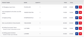
Hoped someone much more knowledgeable would respond to your questions.. I have received the chassis from Modushop, as well as Frank's boards and display. I haven't attatched the display yet.. That said, to answer your questions "Yes" Gianluca did supply the perspex window for my chassis. You'll have to order the chassis "bit by bit" for Franks solution as there isn't a "one stop shop" order for that config. Part of that order was the perspex window. I'll attach a screen shot of all that was required. I ordered the balanced chassis. As far as screwing the display to the chassis, or the perspex.. I don't think it's a great idea. The perspex is approx 3mm and likely thick enough, however the holes in the corners of the display boards are very small. I"d be more concerned about goofing that procedure up vs using silicone and kapton tape. Frank's recommended procedure was to use a dot of hot glue in the corner of the display board somewhere to hold it in the right spot.. Then use silicone to fix it permanently.
Hope this is helpful!
-John
Attachments
Last edited:
Making some good progress on my IP.. Boards built and tested.. Voltages are great.. I"m working on layout now and sorting out my cable strategy. Question about the AC out on Franks logic board.. There are 4 spots, but not labeled.. Is there any specific order for the primary wires? Red/Black/Red/Black? In IAIMH's pic above, it looks like he went B/R/R/B from left to right in the pic? Thanks all!
^ A DMM set to resistance / continuity is your best friend in this situation. Also, the board should be labeled. I think Frank had a few iterations of the boards, so it is best to validate your exact version.
For the "AC In", you should have 3 pads. PE (Protective Earth) and two additional pads for Neutral and Live. Makes no difference whatsoever which pads you select for neutral and live. Neutral and Iive should go directly to your PEM. PE should have a direct connection to the chassis through a conductive standoff. If you're not using conductive standoffs, you can run a wire.
For the "AC Out", you should have 4 pads. The reason I did "red, black, black, red" or "black, red, red, black" (I don't remember) is that for my version the two outer sets of pads were connected by a trace as were the two middle pads. Frank conveniently had 4 pads b/c a lot of people use dual primary transformers and/or may use two transformers for dual mono.
The Antek transformers I used have two primaries and two secondaries. It's a bit picky, but it's important to remember that it's not two "pairs" of primaries and secondaries. Each primary has a "red end" and a black end". I think that confuses a number of people. When properly separated, the "red and black" are the ends of the same windings.

Even though it's not strictly necessary in this situation, I like to ensure that I separate the primaries and twist them together. It makes my life easier, and it helps with noise/hum. So, in most of my builds, you'll see the red end and the black end of the same primary (validated with a DMM) twisted together. Since I'm in a country with 115/120 VAC mains, the Antek transformers with dual primaries need the primaries to be run in parallel to get the appropriate output voltage. I generally validate this prior to connecting the transformer to anything. It's prevented a few nasty situations.

In countries with 230 / 240 VAC mains voltage when using the same transformers, the primaries would be run in series in order to obtain the proper output voltage.

So that wiring would not look like how I did mine.
With 120 VAC, it's not hyper-critical to differentiate the primaries' red and black b/c we're running them in parallel.
With 240 VAC it is absolutely critical to ensure the proper ends of the windings are chosen.
That's a VERY long-winded way of getting around to...
Make sure you know the transformers you're using and the wiring / configuration and "beep it out" and test the transformer output voltage prior to connecting it to a circuit. Many transformer companies use the same color insulation for the end of each primary / secondary. In some cases, the phase will be critical (indicated by phase dots on the yellow sticker on Antek transformers). In your situation, they're not important.
In this case, with two transformers, you could choose to "lump all the reds together, and lump all the blacks together" and it would not make one iota of difference as long as they were connected to one set of outer pads and one set of inner pads on the board. I separated them b/c Frank was kind enough to provide 4 pads, and the terminal blocks I used looked better with the smaller bootlace ferrules (IMO). Plus, if the transformers needed to be separated and used for another project, I wouldn't need to cut the ferrules off.
---------------------------
REALLY short version. You should be absolutely fine. But if it were me, I'd triple check the board to make sure the AC out pads are in the configuration expected.

For the "AC In", you should have 3 pads. PE (Protective Earth) and two additional pads for Neutral and Live. Makes no difference whatsoever which pads you select for neutral and live. Neutral and Iive should go directly to your PEM. PE should have a direct connection to the chassis through a conductive standoff. If you're not using conductive standoffs, you can run a wire.
For the "AC Out", you should have 4 pads. The reason I did "red, black, black, red" or "black, red, red, black" (I don't remember) is that for my version the two outer sets of pads were connected by a trace as were the two middle pads. Frank conveniently had 4 pads b/c a lot of people use dual primary transformers and/or may use two transformers for dual mono.
The Antek transformers I used have two primaries and two secondaries. It's a bit picky, but it's important to remember that it's not two "pairs" of primaries and secondaries. Each primary has a "red end" and a black end". I think that confuses a number of people. When properly separated, the "red and black" are the ends of the same windings.
Even though it's not strictly necessary in this situation, I like to ensure that I separate the primaries and twist them together. It makes my life easier, and it helps with noise/hum. So, in most of my builds, you'll see the red end and the black end of the same primary (validated with a DMM) twisted together. Since I'm in a country with 115/120 VAC mains, the Antek transformers with dual primaries need the primaries to be run in parallel to get the appropriate output voltage. I generally validate this prior to connecting the transformer to anything. It's prevented a few nasty situations.
In countries with 230 / 240 VAC mains voltage when using the same transformers, the primaries would be run in series in order to obtain the proper output voltage.
So that wiring would not look like how I did mine.
With 120 VAC, it's not hyper-critical to differentiate the primaries' red and black b/c we're running them in parallel.
With 240 VAC it is absolutely critical to ensure the proper ends of the windings are chosen.
That's a VERY long-winded way of getting around to...
Make sure you know the transformers you're using and the wiring / configuration and "beep it out" and test the transformer output voltage prior to connecting it to a circuit. Many transformer companies use the same color insulation for the end of each primary / secondary. In some cases, the phase will be critical (indicated by phase dots on the yellow sticker on Antek transformers). In your situation, they're not important.
In this case, with two transformers, you could choose to "lump all the reds together, and lump all the blacks together" and it would not make one iota of difference as long as they were connected to one set of outer pads and one set of inner pads on the board. I separated them b/c Frank was kind enough to provide 4 pads, and the terminal blocks I used looked better with the smaller bootlace ferrules (IMO). Plus, if the transformers needed to be separated and used for another project, I wouldn't need to cut the ferrules off.
---------------------------
REALLY short version. You should be absolutely fine. But if it were me, I'd triple check the board to make sure the AC out pads are in the configuration expected.
- Home
- Amplifiers
- Pass Labs
- Logic Solutions for Iron Pre Kits