As suggested by Zen Mod, I have opened a new thread for discussing logic solutions to replace the original rotary switch and the plain volume pot.
Whether you want to control the relays remotely (Lazy Boyz) or from the front panel using Arduino, ATtiny, ESP32, or any other MCU, this is where to discuss it and ask questions.
Attenuators, whether it's remotely controlled or not, can also be discussed here. In fact, any deviation from the standard rotary input channel switch and/or the standard pot qualifies for discussion here.
Links to important information
The original Iron Pre threads:
https://www.diyaudio.com/community/threads/iron-pre-essentials-kits-for-the-diya-store-register-your-interest.390509
https://www.diyaudio.com/community/threads/whats-wrong-with-the-kiss-boy.293169/
Updated schematics and BOM of the Iron Pre kits: post #1 of the Iron Pre Essentials Kits thread
Modification of current boards (first batch) to allow switching of the relays via microcontroller.
SE version: Post Post #13
BAL version: Post Post #14
There is some valuable information about driving the relays using logic pins on MCU's in the Iron Pre Essentials Kits thread, starting with post #1,232 and maybe even before that.
PS: This post will be updated regularly to include important information.
Last edited:

Yes. I have a soekris Dam 1021 board. I purchased and intend to use an Arduino Due to control it. Will use the internal volume control for the DAC and control with an IR remote. Would also use it to switch between the DAC digital inputs. I picked up the balanced iron pre boards and decided to install the boards in the same enclosure as the DAC. So the Iron Pre will have 2 inputs: DAC Single ended and an external SE Input. I would like to be able to switch between them. Most of my amps have balanced inputs. Not adding volume control for the Iron Pre.
I have looked into it enough to know that what I am planning is possible, but haven't worked out all the details yet or tested out exactly how to do it.
I have looked into it enough to know that what I am planning is possible, but haven't worked out all the details yet or tested out exactly how to do it.
I presume all of you will implement Logic solutions with "low side" switches, where positive rail is common for relays, and each relay is having a switch (bjt, mosfet, darlington) pointed to gnd
when you're ready, ask and I'll give specifics how to accommodate present gen of pcbs for that; these being with GND as common rail, but necessary changes are simple
(next batch of pcbs in Store will have relays having positive rail common and easy implementation of logic instead of rotary switches)
my advice - use separate PSU bot for logic and for relays actuated by logic, do not count on Iron Pre PSU being mated ( in any way) neither with logic nor relays - considering that relays and logic are having same GND
Thanks for the kind offer, ZM. Yes, please give more details of how the present boards can be made to work to switch the relays with logic pins. I suspect that everyone here already, and quite possibly those still joining, have kits from the current batch in their greedy hands, or will soon have. My own SE kit is about a week away.
Edit: What do you mean by "low side" switches? Ah, sorry, you've explained it already. Yes, I'll be using 2N3904 transistors with 2K2 resistors connected to the logic pins of the ESP32. The same should work for Arduino pins.
Edit: What do you mean by "low side" switches? Ah, sorry, you've explained it already. Yes, I'll be using 2N3904 transistors with 2K2 resistors connected to the logic pins of the ESP32. The same should work for Arduino pins.
Last edited:

You could use a small processor, something like a PIC12F1501. 8 pins so it would use 2 for power/gnd, one for source select button then 5 pins left to drive relays. FETs like 2N7000 work great and the PIC can drive them directly. The chip costs about 1 dollar. Oh it also has NV RAM to remember source selection between power cycles. But you would have to buy a chinese knock off PICKit programmer. They are also cheap. Development S/W from Microchip is free. That's what I'd use. Cheap and effective. And once you sort out how to work with it then your world opens to many other possibilities. Or use an Arduino if you like pricey and huge. Just my 2 cents.
The Arduino world has the ATtiny85 that does exactly the same. Also 8 pins and EEPROM to remember stuff like pin states, etc. The nice thing about the ATtiny (there is a whole range of them), is that you do development work on e.g. Arduino Uno, and then port the code to the ATtiny. You can do all of that through a standard USB cable. No expensive programmer required.
Sure, the PIC has it's place, but it's always been too daunting for me. The Arduino opened up a whole new world in micro computing for me in a user-friendly way. And when you need more power, the ESP32 and Teensy are also compatible with Arduino.
Sure, the PIC has it's place, but it's always been too daunting for me. The Arduino opened up a whole new world in micro computing for me in a user-friendly way. And when you need more power, the ESP32 and Teensy are also compatible with Arduino.
Last edited:
here it is:
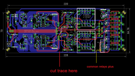
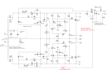
(ZM shouting): HOW TO MAKE PRESENT GEN OF IRON PRE SE PCBS ADEQUATE FOR LOGIC BASED COMMANDS WITH RELAYS POSITIVE COMMON
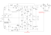
everything is written on pics
you need to do everything written in red
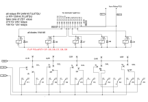
resulting pins for common positive marked on IDC/flat cable connector
numbers 1-5 stay as they are, those being contacts which each of low side switches need to connect to relays PSU GND
(ZM shouting): HOW TO MAKE PRESENT GEN OF IRON PRE SE PCBS ADEQUATE FOR LOGIC BASED COMMANDS WITH RELAYS POSITIVE COMMON
everything is written on pics
you need to do everything written in red
resulting pins for common positive marked on IDC/flat cable connector
numbers 1-5 stay as they are, those being contacts which each of low side switches need to connect to relays PSU GND
Attachments
here it is:
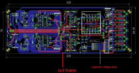
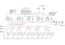
(ZM shouting): HOW TO MAKE PRESENT GEN OF IRON PRE PCBS ADEQUATE FOR LOGIC BASED COMMANDS WITH RELAYS POSITIVE COMMON
everything is written on pics
you need to do everything written in red
resulting pins for common positive marked on IDC/flat cable connector
numbers 1-5 stay as they are, those being contacts which each of low side switches need to connect to relays PSU GND
Attachments
That is kind of what I had figured. Further reduces what I need to collect to complete the build. Just resistors, caps, diodes, and relays. I already have a variety of resistors and diodes. Now to purchase.
If my arduino uses 3.3V logic do I need to power the relays with 3.3V? I do have a 5V supply I could use.
If my arduino uses 3.3V logic do I need to power the relays with 3.3V? I do have a 5V supply I could use.
@wcwc In post #6 Zeb Mod mentioned the three methods for using 3.3V pins to trigger the standard 24V relays (bjt, mosfet, darlington). By using 24V relays, the triggering transistor doesn't have to handle as high a current as would have been the case with 3V or 5V relays. Am I saying it correctly, @Zen Mod? Please correct me if my terminology is wrong. This is fairly new ground for me too.
You would require a separate 24V power source for the relays though, as it's not advisable to use the same 24V supply that the Iron Pre uses.
You would require a separate 24V power source for the relays though, as it's not advisable to use the same 24V supply that the Iron Pre uses.
Boyz, I'm far from being any Guru with Arduino and uprocessors
I gave you what is needed to mate my construction with those above, if you need help understanding and developing logic circuitry, there are Greedy Boyz around doing it in sleep, with weaker hand
if you want to use 3V3 rail and GND of arduino or whatnot - go for it - buy 3V relays and that's it
if you want to use 5V rail and GND of arduino or whatnot - go for it - buy 5V relays and that's it
if you have 12V relays, besides arduino and whatnot, all you need is additional 12V rail, sharing GND with Arduino and whatnot
if you have 24V relays, besides arduino and whatnot, all you need is additional 24V rail, sharing GND with Arduino and whatnot
I mean - be real - if, with some mild effort, someone isn't able to arrange logic and remote, just stay with rotary switches
Boyz, I'm far from being any Guru with Arduino and uprocessors
I gave you what is needed to mate my construction with those above, if you need help understanding and developing logic circuitry, there are Greedy Boyz around doing it in sleep, with weaker hand
And we thank you for that. The rest we'll figure out. I've been dabbling with Arduino for more than a decade, but don't profess to be a guru either. Fortunately, there is a huge Arduino community with lots of online information.
- Home
- Amplifiers
- Pass Labs
- Logic Solutions for Iron Pre Kits