I did but i saw at the first page of the data sheet this..."Wide supply range 20V - 94V". ( http://www.ti.com/lit/ds/snas091b/snas091b.pdf)
So I am lost
Please guide me.
Best regards,
Som
So I am lost
Please guide me.
Best regards,
Som
Okay, what is the suitable transformer for my amp ? Sorry if I missed the earlier posts. I want to use 4 X 4700 ufd.
Best regards,
Som
Best regards,
Som
15Vac+15Vac upto 27Vac+27Vac is usable if you ensure that Vdc <=42V.
If you use lower than 8ohms speakers then the upper limit becomes 22Vac+22Vac
Your 63V capacitors are a waste of resources for an amplifier that cannot operate above 42Vdc.
25V, 35V & 40V capacitors can be used with chipamps, if you ensure your worst case operating voltage is below the maximum for the capacitor you choose.
Thank you Andrew. I think i will start with a 15Vac+15Vac at first to be on the safe side since I intend to do bi-amping.
My tweeters are of 4 Ohms.
Best regards
Som.
P.S. I just found an old 12-0-12 @ 4 amp 😀
I might use that as a test 🙂
My tweeters are of 4 Ohms.
Best regards
Som.
P.S. I just found an old 12-0-12 @ 4 amp 😀
I might use that as a test 🙂
Can I somehow re-modefy the schematic for 40W max out? My speakers are bass=60w, mid=50w and high=50w. I don't want to damage them, and what power would i need to use then? Thanks for the reply.
Can I somehow re-modefy the schematic for 40W max out? My speakers are bass=60w, mid=50w and high=50w. I don't want to damage them, and what power would i need to use then? Thanks for the reply.
There is no need for this. The speakers draw as much current as they need.
You can install a 1000W amp at this speaker and - provided you don´t listen TOO loud, the speakers will be fine. The amps power rating only means the maximum available power, not the one that is used on (normal 🙄) listening levels.
In my opinion, more power recources from the amp are never a bad idea.
However, if you know the impedance of your speakers, you can check the datasheet of the LM3886 and reduce the transformer voltage (and consequently the operating voltage of the chip). So with a given voltage, you only get a certain maximum output power.
But again, I would rather try to maximise the output power for a given speaker impedance, meaning about 20V-22V Transformers for 4 Ohm speakers and about 25V-27V (?) volt ones for 8 Ohm speakers.
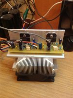
my LM3886
An externally hosted image should be here but it was not working when we last tested it.
Nice work
my LM3886
Do you have a picture of the bottom side of the board?
Last edited:
I've been running my LM4780, which is 2 x LM3886s in one package, and driving 4 ohm speakers (CSS EL70) for 6 months or more without any problems. Depends how load you want to listen to your music. The power supply is 22-0-22 AC which gives a DC rail voltage of about +/-30v after the rectifier.
The sound is very good and clear, especially paired with my DIY DAC and my super-tweeters. It doesn't run too hot, and I am still amazed at the quality of audio it produces. I definitely recommend building a LM4780 or LM3886 chip amp, you will not be disappointed 🙂
Here is the amp and DAC:
http://www.diyaudio.com/forums/chip-amps/79303-chip-amp-photo-gallery-219.html#post3119597
http://www.diyaudio.com/forums/chip-amps/79303-chip-amp-photo-gallery-236.html#post3353545
Here are my speakers:
http://www.diyaudio.com/forums/full...ge-speaker-photo-gallery-218.html#post3152149
and here are the tweeters I built to accompany the full range drivers as they lacked a little top end:
http://www.diyaudio.com/forums/multi-way/226786-adding-super-tweeter-full-range-11.html#post3328360
Hi all,
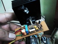
I made the LM3886 in a PCB as per Apex's design with so much optimism but alas! It's not working for me. 🙁 I am lost where I made the mistake.
I powered it up with a 15-0-15 VAC 2 amp transformer . Voltages are okay. But no sound, no hum. Total silent.
Is the IC faulty?
Need your kind suggestion/guidance to make it work.
Thank you.
Attachments
Have you got a 10K resistor from -ve to the mute pin? Without this, the chip will be muted
Also, have you fed the board with 15-0-15 AC, or have you rectified it to give you +-21V DC?
Also, have you fed the board with 15-0-15 AC, or have you rectified it to give you +-21V DC?
Last edited:
Thank you so much Port... for your prompt reply.
I double checked the 10k Resistor and pin 8 and the zener diode. All okay as it seems.
Sure, the supply supply is rectified dual with 4700 uF X 4
Very strange. Is there anything more that I should check before changing the Chip?
I double checked the 10k Resistor and pin 8 and the zener diode. All okay as it seems.
Sure, the supply supply is rectified dual with 4700 uF X 4
Very strange. Is there anything more that I should check before changing the Chip?
Last edited:
The circuit is pretty simple, there isn't that much to go wrong. Have you got any voltage at all on the output? I don't use a Zener diode on the mute pin, I simply use a 10k resistor from -ve to it as in the LM3886 datasheet. You could try removing the Zener diode from the circuit and link it with a wire.
.........Have you got any voltage at all on the output? I don't use a Zener diode on the mute pin, I simply use a 10k resistor from -ve to it as in the LM3886 datasheet. You could try removing the Zener diode from the circuit and link it with a wire.
Ohh! I will remove the zener too and report you back with voltages at various pins, in some hours.
Thank you really so much!
- Home
- Amplifiers
- Chip Amps
- LM3886 Schematics + PCB