With D2 reversed you were dumping DC from the power supply into the trace that is the output of the amp. So the feedback resistor did its job and dumped DC into the input of the amp, a lot of DC, and the amp tried to amplify the DC signal. So you were dumping full volume DC out of the amp. I think this is what happened and why you had it heating up so fast.
With D2 reversed you were dumping DC from the power supply into the trace that is the output of the amp. So the feedback resistor did its job and dumped DC into the input of the amp, a lot of DC, and the amp tried to amplify the DC signal. So you were dumping full volume DC out of the amp. I think this is what happened and why you had it heating up so fast.
But even after all this, nothing has happened to the chip yet! 😱
Its a pretty awesome chip. Hard to hurt and hard to get bad sound out of it. Fun to play with and a great amp to learn some basics about power amps and opamps at the same time. Also a great reference. If you have a LM3886 or similar chip and you make an amp then its a good reference to compare any other amps you build/design to.
Just slapped it together to see how it sounds,
And must say lovely small pcb and amp.
Thanks
Ill put a decent heatsink on it later 🙂
Nice work
Regards
Hi apex,
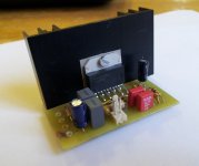
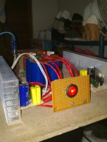
this is my LM3886T project, and nice combine with my new small speaker 6" 😀
BR,
Nice work,
Regards
Nice work,
Regards
Hi Apex,
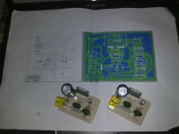
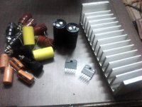
i want to ask about component for this Amp,
how much difference sound, if using good quality components or using component like i used at the picture? only poor ceramic capacitor, and other.
i need advice for that, before plan to buy good quality component,
have much different or not, because for now the sound is good enough.
thanks Apex,
BR,
Hi Apex,
i want to ask about component for this Amp,
how much difference sound, if using good quality components or using component like i used at the picture? only poor ceramic capacitor, and other.
i need advice for that, before plan to buy good quality component,
have much different or not, because for now the sound is good enough.
thanks Apex,
BR,
anybody, can help me?? 😀
Most of your components look fine.
You might want to try to fit 1uF or more (or less) of film cap directly between each of the chip's power rail pins and the main power ground trace, connected VERY close to each power pin. If you could also get 220 uF (or as much as possible) connected directly at each power pin, and to the main power ground, that would be very good, too.
With the film caps, unless you have a scope you will want to initially look for signs of oscillation, in case you get unlucky (e.g. excessive chip heating). But without SOME small cap connected directly at each power pin, to gnd, you increase the risk of high-frequency oscillation. If film won't work, use ceramic, but not the "good" ones like C0G or NPO; you would want a little more loss, to damp any oscillation tendency.
Most of your components look fine.
You might want to try to fit 1uF or more (or less) of film cap directly between each of the chip's power rail pins and the main power ground trace, connected VERY close to each power pin. If you could also get 220 uF (or as much as possible) connected directly at each power pin, and to the main power ground, that would be very good, too.
With the film caps, unless you have a scope you will want to initially look for signs of oscillation, in case you get unlucky (e.g. excessive chip heating). But without SOME small cap connected directly at each power pin, to gnd, you increase the risk of high-frequency oscillation. If film won't work, use ceramic, but not the "good" ones like C0G or NPO; you would want a little more loss, to damp any oscillation tendency.
Mr.Gootee
thanks for your best answer,i will try using more than 1uF metal film caps,
for 220uF and 10uF at schematic, can i use more bigger volt value more than 160V?how about impact to the sound?
at my kit, using 220uF/160V and for 10uF still using 10uF/25V (will change with 160V 😀).
one more sir,
i have plan to build subwoofer amp and kit.
if i use bridge LM3886 for sub and this kit for normal speaker,
how about the sound produce, if see the amp have same character?
or using different type like TDA?
nb: sorry for my English 😀
BR,
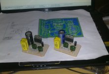
Hi Apex,
This is update for my LM3886 amp, no box there 😀
PSU using 10000uF x 4, 😀
and with Trafo 3 Ampere (so only 36 watt per-channel) 🙁
BR,
Nice work, 36W is enough for home listening.
Bridging of amplifiers brings in a whole lot of difficult design issues.
These design issues (compromises?) are particularly demanding of chipamps which are inherently strangled for current output.
Take a simple 68W into 8ohms chipamp.
The output voltage and current for 68W is 23.3Vac along with 2.9Aac. Not much of a problem.
The peak current into a 8r0 test load is similarly not much of a problem: 4.12Apk
Well below the guaranteed minimum of a cold operating 3886 (>=7A).
But speakers particularly passive crossovered speakers do not draw the same currents as resistive dummy test loads.
Expect at least twice the peak current on fast transients when driving a 8ohms speaker. Some demanding music can easily require three times as much current to be sent to the speaker and some speaker/music tests reported and linked on this Forum measured in excess of five times.
Just using the 3times results in transient peak currents of around 12Apk. That is well in excess of what a 3886 can supply when cold.
Bridging doubles the output power into double the load impedance.
If we have a pair of 68W into 8r0 chipamps, then we will get 136W into 16ohms when bridged.
But we don't generally use 16ohms speakers.
We use 8ohms and 6ohms and 4ohms speakers.
Do the same numbers for these "normal" speakers and you find that bridged chipamps can't supply the currents that the speakers demand. That's why National show a BPA configuration (Or is it to sell 6times as many chips to the gullible builder), just to supply current to a dummy test load. Their arrangement stills falls well short of meeting the current demands of real speakers.
Last edited:
Bridging of amplifiers brings in a whole lot of difficult design issues.
These design issues (compromises?) are particularly demanding of chipamps which are inherently strangled for current output.
Take a simple 68W into 8ohms chipamp.
The output voltage and current for 68W is 23.3Vac along with 2.9Aac. Not much of a problem.
The peak current into a 8r0 test load is similarly not much of a problem: 4.12Apk
Well below the guaranteed minimum of a cold operating 3886 (>=7A).
But speakers particularly passive crossovered speakers do not draw the same currents as resistive dummy test loads.
Expect at least twice the peak current on fast transients when driving a 8ohms speaker. Some demanding music can easily require three times as much current to be sent to the speaker and some speaker/music tests reported and linked on this Forum measured in excess of five times.
Just using the 3times results in transient peak currents of around 12Apk. That is well in excess of what a 3886 can supply when cold.
Bridging doubles the output power into double the load impedance.
If we have a pair of 68W into 8r0 chipamps, then we will get 136W into 16ohms when bridged.
But we don't generally use 16ohms speakers.
We use 8ohms and 6ohms and 4ohms speakers.
Do the same numbers for these "normal" speakers and you find that bridged chipamps can't supply the currents that the speakers demand. That's why National show a BPA configuration (Or is it to sell 6times as many chips to the gullible builder), just to supply current to a dummy test load. Their arrangement stills falls well short of meeting the current demands of real speakers.
Has anyone ever tried adding a discrete-transistor "current booster" or power-booster circuit to a chipamp? On second thought, in that case we probably might as well just use a good opamp in place of the chipamp, unless maybe we wanted to try to configure the current booster to engage only when needed.
For power-booster/current-booster application notes with schematics:
Go to Linear.com and search for AN-18.
Go to national.com and search for AN-272.
One could also google for "current dumping amplifier".
Starting my first LM3886 bi-amping
I bought some components yesterday.
Is the size of the heatsink ( 6 cm X 17cm) okay to mount two LM3886 ICs for proper heat dissipation?
Best regards,
Som
I bought some components yesterday.
Is the size of the heatsink ( 6 cm X 17cm) okay to mount two LM3886 ICs for proper heat dissipation?
Best regards,
Som
Attachments
Last edited:
60 by 170 should be enough for a pair of 3886. But check the National datasheet for their guidance.
Then I recommend you double what they say.
Then I recommend you double what they say.
Thank you Andrew.60 by 170 should be enough for a pair of 3886. But check the National datasheet for their guidance.
Then I recommend you double what they say.
Also I have a 30-0-30 @ 5amp Transformer. Can I use that with 4 X 4700 uFd 63 v in the PSU ?
Best regards,
Som
Attachments
- Home
- Amplifiers
- Chip Amps
- LM3886 Schematics + PCB