I'm building my power supply now with the HV lm317's and having an odd problem. The positive rail gives me the right voltage output for the given equation but the negative rail using the same resistor values is outputting 10 less volts for some reason. I'm also using the 2n3055 power transistors to increase the current output. I know the Lm317 are a positive regulator but why would I have the issue?
So my question is how would I configure the lm317 in the negative supply rail? Because the negative acts as the positive and vice versa. Right now I have the positive lead from the cap feeding into the negative pin on the 317, and the Vin from the negative rail.
You can't configure the LM317's as a negative supply.
All you can do is have two complete positive supply's and tie them in series as mentioned earlier providing that they are fed each from their own LV winding and are isolated from each other.
Please post the schematic that you are working with.
Did you include an opamp as I have shown in post #40.
Without this opamp the load regulation is pretty bad.
I have not tried the other version yet using a PNP small signal to drive the 2N3055 yet but simulations show that it is not that great either so I never messed with it as I had explained in my last post.
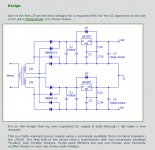
Basically what you need to do is set it up like this supply as this is just an example so don't let it confuse you.
http://www.ko4bb.com/Manuals/08)_Misc_Ham_Equipment/Micronta_22-121_Service_Manual.pdf
I have one of these and one side went out and I had to use a different regulator to make it work again (LT3081) and I have not figured out how to make it dual tracking again,But it is on my list of things to finish though.
Basically it is two Positive Regulated supply's that are tied in series to make a bipolar supply and I still use it as such with no issues of the regulators drifting in a bipolar configuration.
I just have to manually set the voltage of each side is all, until I figure out the dual tracking part.
It would be much simpler if TI made an HV version of the LM337, but they don't!! 🙁
The circuit must be wired like this in order for it to work (see pic.),
Building an LM3886 Gainclone chip amp with a regulated power supply (PSU).
I will post my Final circuit that I have made for the regulator although I have not made the HV version yet but all that will be required is the use of an HV opamp such as an LTC2057HV in place of the LT1001.
jer 🙂
All you can do is have two complete positive supply's and tie them in series as mentioned earlier providing that they are fed each from their own LV winding and are isolated from each other.
Please post the schematic that you are working with.
Did you include an opamp as I have shown in post #40.
Without this opamp the load regulation is pretty bad.
I have not tried the other version yet using a PNP small signal to drive the 2N3055 yet but simulations show that it is not that great either so I never messed with it as I had explained in my last post.
Basically what you need to do is set it up like this supply as this is just an example so don't let it confuse you.
http://www.ko4bb.com/Manuals/08)_Misc_Ham_Equipment/Micronta_22-121_Service_Manual.pdf
I have one of these and one side went out and I had to use a different regulator to make it work again (LT3081) and I have not figured out how to make it dual tracking again,But it is on my list of things to finish though.
Basically it is two Positive Regulated supply's that are tied in series to make a bipolar supply and I still use it as such with no issues of the regulators drifting in a bipolar configuration.
I just have to manually set the voltage of each side is all, until I figure out the dual tracking part.
It would be much simpler if TI made an HV version of the LM337, but they don't!! 🙁
The circuit must be wired like this in order for it to work (see pic.),
Building an LM3886 Gainclone chip amp with a regulated power supply (PSU).
I will post my Final circuit that I have made for the regulator although I have not made the HV version yet but all that will be required is the use of an HV opamp such as an LTC2057HV in place of the LT1001.
jer 🙂
Attachments
Here's what I'm implementing to my power supply
http://3.bp.blogspot.com/-Y-mEVC4YX...igh+current+variable+power+supply+circuit.png
The negative aspect threw me off, I tried to configure it backwards to create a negative supply.
http://3.bp.blogspot.com/-Y-mEVC4YX...igh+current+variable+power+supply+circuit.png
The negative aspect threw me off, I tried to configure it backwards to create a negative supply.
That is the same circuit that I have been working with only using more transistors.
It's load regulation is not very good.
I tried adding a resistor from the output to the adjust input to the LM317 and this help but it still was not rock solid.
So, I added a simple opamp and a new Vref and the thing is rock solid now and it does not drift what so ever!!
I have had it on for days and it has never drifted even when a heavy load is connected to it drawing as much as 3 or 4 amps!!
My only limiting factor at this point is the small transformer I am using.
The noise out of the circuit I am purposing is very very low and as long as the transformer can supply the current at its set voltage there is no ripple or droop in the output voltage.
The residual noise is lower than what I can measure at this time.
The noise floor of my surroundings is somewhere around 140uv rms and lower, I can't even tell when the supply is turned on even under a 3.5 amp load with my scope set at its highest sensitivity at 1mv per division.
This turned out nicely and better than I expected.
Thank you for putting me up to this, I plan on making a PIC controller to build a few channels of programmable bench supply's with this circuit.
I will also build the HV version as well to verify that it works too and give it a real test of abuse providing I can find something that will be a suitable high power load resistance.
Otherwise I don't for see any issues with this circuit as is.
I have been testing it under many stressful conditions since I have made it.
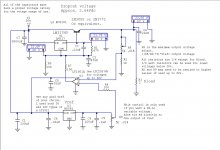
Here is my final circuit with some notes.
R2 & R9 may need to be resized to higher values so that they don't burn up as per Ohm's law.
They don't need any significant amount of current flowing through them as they are just voltage dividers that provide for a gain adjustment (feedback) of the circuit to set the highest voltage level at the output.
I tried to keep them at a lower value in order to keep the residual noise and input impedance to the opamp at a minimum.
Cheers !!!!
jer 🙂
P.S. I am glad you have figured out your issue with how it works. 🙂
It's load regulation is not very good.
I tried adding a resistor from the output to the adjust input to the LM317 and this help but it still was not rock solid.
So, I added a simple opamp and a new Vref and the thing is rock solid now and it does not drift what so ever!!
I have had it on for days and it has never drifted even when a heavy load is connected to it drawing as much as 3 or 4 amps!!
My only limiting factor at this point is the small transformer I am using.
The noise out of the circuit I am purposing is very very low and as long as the transformer can supply the current at its set voltage there is no ripple or droop in the output voltage.
The residual noise is lower than what I can measure at this time.
The noise floor of my surroundings is somewhere around 140uv rms and lower, I can't even tell when the supply is turned on even under a 3.5 amp load with my scope set at its highest sensitivity at 1mv per division.
This turned out nicely and better than I expected.
Thank you for putting me up to this, I plan on making a PIC controller to build a few channels of programmable bench supply's with this circuit.
I will also build the HV version as well to verify that it works too and give it a real test of abuse providing I can find something that will be a suitable high power load resistance.
Otherwise I don't for see any issues with this circuit as is.
I have been testing it under many stressful conditions since I have made it.
Here is my final circuit with some notes.
R2 & R9 may need to be resized to higher values so that they don't burn up as per Ohm's law.
They don't need any significant amount of current flowing through them as they are just voltage dividers that provide for a gain adjustment (feedback) of the circuit to set the highest voltage level at the output.
I tried to keep them at a lower value in order to keep the residual noise and input impedance to the opamp at a minimum.
Cheers !!!!
jer 🙂
P.S. I am glad you have figured out your issue with how it works. 🙂
Attachments
Last edited:
Thanks Gerald, rewired things and now everything is working like it should. Well I haven't tested it under any load yet but my main objective was to reduce voltage without reducing my current.
Last edited:
That is Great to hear!!!
Keep me posted as to the performance of your setup and any modifications you do along the way!!!

jer 🙂
Keep me posted as to the performance of your setup and any modifications you do along the way!!!
jer 🙂
Hey Gerald, If I add 3 of the lm317s in parallel that's could also work to increase the current as well? I made a rookie mistake a blew one of my 2n3055's so I have to either order more or try multiple 317's. The 2n3055 are quite bulky as well.
Well I have though about that but the issue is getting them all synced together at exactly the same voltage.
Typically it has been shown it is possible especaily with the fixed types but i have never seen it actually done with the variable LM317's.
However LT has a lot of this in their app notes even with their variable devices but there is usually some kind of tracking opamp involved to help eliminate any current hogging between the devices.
What happened?
You must put that transistor on a heat sink you know!!
Your voltage drop across the regulator times the output current will determine the power dissipation that the transistor has to do.
In your case this should be fairly low unless you are asking it to drop more than a few volts or so even up to 10 amps.
jer 🙂
Well I have though about that but the issue is getting them all synced together at exactly the same voltage.
Typically it has been shown it is possible especaily with the fixed types but i have never seen it actually done with the variable LM317's.
However LT has a lot of this in their app notes even with their variable devices but there is usually some kind of tracking opamp involved to help eliminate any current hogging between the devices.
What happened?
You must put that transistor on a heat sink you know!!
Your voltage drop across the regulator times the output current will determine the power dissipation that the transistor has to do.
In your case this should be fairly low unless you are asking it to drop more than a few volts or so even up to 10 amps.
jer 🙂
I made the dumb mistake of connecting positive and negative backwards when connecting it to my amp. Only one is bad and I ordered a replacement
Ohhh!!!!
That don't work to good!!!
Hopefully you will get to test it properly this time around.
Don't feel bad,
While I was designing and testing my version I had a wire hanging off of the board and it touch the 120v hot side of the transformer and it took out the LM317 a cap and a the LT1001!!
And later the LT1021 went out too for some reason.
So I swapped that to a 10 volt version because that is what I had on hand.
Then later on I had it running for testing of the noise level and drift so it ran for days with no issues.
Then the next morning I turned it on and there was no voltage!!
As it turned out it was shorted by some clip leads that I forgot where hooked up and that over heated and blew out the original 2SD266 that I was using.
So, I had to find a bigger heat sink and a TO-3 model type of NPN power transistor drill the case out and mount them.
But since then it has been working flawlessly now!!
The bigger heatsink sure helped a lot too, as it barely gets warm when it is shorted now.
jer 🙂
I'm not sure what's up with the 2n3055 transistor. So I reconfigured my power supply using only one transistor per rail, because I ruined the other two. So under no load conditions my power supply was working. I soon as I plugged it in to my amp, correctly this time, it stopped working immediately, and now it seems my last transistors are not working...
I was only using two per rail as the circuit diagram called for three for 10 amps, and my transformer doesn't output that many amps, only 4.16 per secondary.
I was only using two per rail as the circuit diagram called for three for 10 amps, and my transformer doesn't output that many amps, only 4.16 per secondary.
Last edited:
Hmmmm..........
If you are using multiple transistors then you probably need to include some emitter resistors to prevent current hogging.
Also they must have a matching "hfe" as well.
They only other thing I can think of is that maybe the Vbe (emittor base voltage) is being exceeded.
The Vbe for the 2N3055 is 7v max.
I will look into LTspice to see what is going on.
Typically 2N3055's are good for up to 60v Vce but I have read in some threads of some mentioning that they are only good for up to 40V or so, but the specs to do say 60v.
The version I have in my supply is unmarked as it is now rusted and it came from a NCR mainframe regulator board and it has NCR part number that I can't find a cross to any more.
Typically all of these were 2N3055's back in the day or where their industrial counterparts.
Anyhow, When I First tested this part it was not mounted and I almost burned it up as this is when I discovered the short clip leads and it survived.
It was very very hot and it burned my thumb when I grabbed it !!!
It has 3 times the hfe at 47 than that of the original 2SD266 that had at an hfe of 15 and this is good to keep the driving current for the LM317 well under its maximum current capability's.
I had found (as I posted earlier) that when you draw current form the circuit that the output voltage goes down as more current is drawn from it.
Since the LM317 can't track this this it is holding solid at its voltage and could be what is causing if the Vbe to be exceeded, if this is the case.
I will look into this.
Check also that the chipamps are not shorted as well.
The conditions you are describing almost sounds like it is shorting the supply!!
Does the supply still work after you disconnect the amp?
jer 🙂
P.S. All of the problems I has described in my Previous post while designing the circuit that I posted were due to operator error as I had described, and it is working very solid.
I will try some more short circuit tests at the risk of losing the transistor, But I haven't had any issues since I upgraded the part with moderate and intermittent shorts yet, since I finished it.
But then again I am only using a smaller 18Vac transformer too.
Last edited:
No, neither rail is working. They don't get hot with an input of 44 volts, not even warm. How can the base be only 7 volts? It's fed directly from the lm317 pins output, which is at 38 volts now.
I don't think my amp has a short anywhere as It was working the last time I tried it. I had just placed an order from jameco for only 2 more transistors so now I'm screwed and have to place another order or figure something else out.
If I had just bought the right transformer from the get go lol
Unless I hooked the transistors up wrong, which I did at first when testing it and there was no output, the collector is the hole metal frame.
Last edited:
Here is another circuit exactly like we are discussing.
0-28V 6-8A Power Supply (LM317, 2N3055)
I noticed the use of the Diodes in order to offset the 1.25v minimum output of the LM317.
I have thought about doing this to allow the output voltage to go all of the way to 0v, But I have not tried it yet.
If this works it is easier than trying to implement a -V that is required to make the LM317 into a true 0V to+ V output regulator when you don't have a means to do so.
Finding this does show that it should be working fine, but it doesn't cover the Load regulation issues I have discovered with this circuit.
FWIW
jer 🙂
Here is one more circuit of this type from the very same designer,
13,8 Volt 20A Power Supply - Schematic Circuits Elektropage.com
The reason I am posting this is because it shows all of the circuits component values.
I was wondering about the Value of R7 in the previous version I just posted and it shows here that a 2.2k is used.
It is various configurations of this resistor I tried and it some what improved the load regulation of the circuit if I had it going from the output of the supply (emitter) to the Vadj pin of the LM317.
I will experiment with this more once I start on a new HV version.
Being that these configurations were offered by a HAM I don't see any reason to question the integrity of the circuit for general use of operation.
I will keep plugging at this myself as well, as I too need a working version for my 49.5Vdc supply's for chipamps.
jer 🙂
Last edited:
No, neither rail is working. They don't get hot with an input of 44 volts, not even warm. How can the base be only 7 volts? It's fed directly from the lm317 pins output, which is at 38 volts now.
I don't think my amp has a short anywhere as It was working the last time I tried it. I had just placed an order from jameco for only 2 more transistors so now I'm screwed and have to place another order or figure something else out.
If I had just bought the right transformer from the get go lol
Unless I hooked the transistors up wrong, which I did at first when testing it and there was no output, the collector is the hole metal frame.
It is not that the base is at 7 volts or greater.
It is the difference of the voltage across the Base and the Emitter that can not be exceeded.
Last edited:
Gerald, how exactly is the grounds connected with the lm3886? I think I heard the pin 7 goes to +ground, but also heard both grounds are connected to create a star ground.
Yes, Pin 7 is ground.
This would be the middle connection of the two supplies where they are tied in series (-V of V1 and +V of V2).
Here is the data sheet,
http://www.ti.com/lit/ds/symlink/lm3886.pdf
There are no other connections on the chip itself that go to ground.
Other than that there are two pins that go to -V (or -V2), PIN 4 goes to -V and the mute pin PIN 8 goes to -V (or -V2) through a resistor.
Pins 1 & 5 go directly to +V ( or +V1).
jer 🙂
Yes, Pin 7 is ground.
This would be the middle connection of the two supplies where they are tied in series (-V of V1 and +V of V2).
Here is the data sheet,
http://www.ti.com/lit/ds/symlink/lm3886.pdf
There are no other connections on the chip itself that go to ground.
Other than that there are two pins that go to -V (or -V2), PIN 4 goes to -V and the mute pin PIN 8 goes to -V (or -V2) through a resistor.
Pins 1 & 5 go directly to +V ( or +V1).
jer 🙂
Lol no I guess I explained it bad. I read in some thread, which I can't seem to locate now, that talks about special things that you must do with the ground connections with this chip. Like pin 7 going to only +ground and the ground for the speaker being isolated or something
- Status
- Not open for further replies.
- Home
- Amplifiers
- Chip Amps
- Lm3886 problem