The LM117/317 HV series is capable of a higher input voltage of 60V max.
LM317HV | Single Channel LDO | Linear Regulator (LDO) | Description & parametrics
It could be used in the Decibel Dungeon design, which is the second link I posted.
As they are only rated at 1.5 amps you can either parallel a few of them or add a extra pass transistor in order to handle more current.
I have done this with the LM317's and it works well.
Since you only need to drop a few volts the power dissipation in the regulator won't be too high.
LT doesn't have any regulators that can handle anything over a rating of 45V and their models for that voltage range can only handle 500ma or less so a series pass transistor would still be required as well.
These links can give you an idea of regulator design and many examples of how to add a series pass transistor.
https://www.google.com/search?num=1....10.0....0...1c.1.52.hp..0.17.712.9yedqO4oynk
https://www.google.com/search?q=vol...9Ho2wggTXuILADg&ved=0CB8QsAQ&biw=1024&bih=678
Typically you can just use a 2N2955 transistor to any LM317 or Lm78xx circuit but it is a PNP type and may be getting harder to find.
A common NPN power type can be easily adapted instead with the addition of a small signal pnp transistor as well.
Regulators aren't really that hard to design but it does add to cost and complexity of your final circuit.
I have searched this heavily myself for a similar/same exact application but there just aren't many ready made chips out there to handle such an application, mainly not for the current rating required anyhow.
jer 🙂
I was going to use the lm317 for the other circuits I intend to add to my amp project. But my concern is the current like you mentioned. I'll check out the links you posted as adding the lm317 in parallel might do the trick.
You must use the "HV" type as they are the only ones rated for a 60Vdc input voltage!!
http://www.ti.com/lit/ds/symlink/lm317hv.pdf
A regular LM317 is still only rated for 40Vdc.
http://www.ti.com/lit/ds/symlink/lm317.pdf
FWIW
jer 🙂
http://www.ti.com/lit/ds/symlink/lm317hv.pdf
A regular LM317 is still only rated for 40Vdc.
http://www.ti.com/lit/ds/symlink/lm317.pdf
FWIW
jer 🙂
Um... Folks... While it is true that the peak of a sine wave is sqrt(2)*Vrms, the actual output voltage of the rectifier circuit will be less than sqrt(2)*Vrms due to the finite conduction angle of the rectifier diodes.
At no load, you'll see close to sort(2)*Vrms on the output of the rectifier, but under load, the DC voltage droops to more like 1.3*Vrms as the diodes conduct for longer time (larger conduction angle).
I agree with others that you may be pushing it a bit, but probably not as badly as you think.
Your main problem is that you don't have a heat sink on the LM3886 (or the one you have is tiny). This problem is exacerbated at high rail voltages because the chip dissipates more power under those conditions.
Also, don't forget to do the math for high mains voltage (assume ±10 % variation). You don't want the amp to go *POP* if the mains voltage is a bit towards the high side one day...
~Tom
Can a CRC filter be of any help to reduce the voltage? e.g. say R=10 (little less or more, power dissipation being taken care off using hefty wattage ratings). No compromise on heatsinks though!
Last edited:
I'm only using the small heat sink for the testing phase, which is when the cutoff issue started to occur. I figured the chip would turn off for a longer duration until it cooled to a suitable operating temperature.
Now for the HV lm317, will this be suitable for the negative rail?
Now for the HV lm317, will this be suitable for the negative rail?
Quote~ "Now for the HV lm317, will this be suitable for the negative rail?"
It won't work for the negative rail.
But, if your transformer has to separate secondary winding's as shown on the DD website then yes you can use it for the negative rail as well.
By having two separate winding's you will have two completely isolated supplies and then they are tied in series for a bipolar supply configuration.
If your transformer is a 30V-0V-30V center tapped type then, No, it won't work. 🙁
jer 🙂
Quote~ "Now for the HV lm317, will this be suitable for the negative rail?"
It won't work for the negative rail.
But, if your transformer has to separate secondary winding's as shown on the DD website then yes you can use it for the negative rail as well.
By having two separate winding's you will have two completely isolated supplies and then they are tied in series for a bipolar supply configuration.
If your transformer is a 30V-0V-30V center tapped type then, No, it won't work. 🙁
jer 🙂
Yeah mine has two secondaries at 30+30 volts, or two separate rails. Sweet I already ordered the HV lm317 from Ti, but I'll have to wait until I get my school money before I can order the 2n3055 transistors
for the high current power supply.
Thanks guys, I appreciate all the help and feedback.
Awesome!!!!!
I am looking forward to seeing your results!!!
I too am going to get some of those LM317HV's as well.
jer 🙂
I am looking forward to seeing your results!!!
I too am going to get some of those LM317HV's as well.
jer 🙂
Last edited:
Can a CRC filter be of any help to reduce the voltage? e.g. say R=10 (little less or more, power dissipation being taken care off using hefty wattage ratings). No compromise on heatsinks though!
A CRC doesn't really help because its the no-load voltage that's too high for the chip and resistors only drop volts when current flows through them.
@Tom - you did not mention the trafo's regulation which increases the off-load voltage by (for a 250VA toroid) 7-10%.
I was messing with a LM317T today as I needed to rebuild one of my Bench supply's that went out.
One thing that I did notice about the LM317 is that the more current you try to draw from it, the lower the voltage drops.
I believe that the cause of this is due to the internal series resistor and it is non-linear.
Because of this issue LT as done away with this resistor in their design of regulator chips.
However I am using it in my supply and I did rebuild it using this simple circuit,
Build an Adjustable 0-34 volt power supply with the Lm317
I am using the original 2SD226A that was in my supply as it is basically the same as a 2N3055 but only a smaller 40v version in a TO-66 package.
I am able to pull 3 to 4 amps out of the supply at 12v with only a 1 or 2 volts drop as 3 amps for 12v and 4 amps at 13.3 volts or so.
The transformer I am using is only rated at 18V and 2 amps.
and the supply adjusts from .825V to 24 volts for lower current ratings.
I do get an amazing peak of about 4.45 amps with the little transformer and the 2SD226A that is in it.
This post is not about my supply but about the performance of the circuit I posted above.
I am quite impressed with its simplicity and its performance.
If I did have it hooked to a larger transformer I am sure that it would provide much more current at the higher end of its voltage adjustment as well.
I will also try this exact same circuit using my 35V 5 amp transformers and a LM317HV as a test for a chipamp regulator and see how it goes and let you know.
The effect of the voltage dropping as more current is drawn has a lesser effect with the added power transistor but it is still there.
This is because I have about a maximum of .22A flowing through the LM317 instead of the original 2.2A I was getting without the transistor.
I calculate the internal resistor to range from .3 ohm to as high as .8 ohms or so depending on how much current was drawn.
I am sure the effect of other internals had to do with this as well.
The the higher the current the higher the value I calculated of the resistance through the regulator itself and this in turn effects the voltage reference voltage ratio set by the two external resistors.
I have read many posts asking this very same question as to why this is, but it was never answered.
However it is explained in one of LT's app notes.
This can be easily remedied by feeding the LM317 with an opamp correction circuit and another voltage reference, I have done this in my Variable HV supply and it works well as it is extremely stable and rock solid.
I am still debating on doing this to my bench supply as it does bother me somewhat, as it does change at the higher voltage settings with only less than 100ma drawn form it as well, not as bad, but it does change.
But this is definitely something that one should be concerned about for an amplifier as you don't want your supply voltage to fluctuate as the current draw changes.
I used a 4700uf capacitor and a 2200uf capacitor in the filter for a total of 6900uf and I was very impressed to have only 12mv p-p or so and not more than about 20mv p-p of ripple at a 4.4 amp current draw from the regulator at 13.5V.
The supply was originally made for 12v operation anyhow but never produced 4 amps before !! 😀
After I had got everything properly RF decoupled, the residual noise no more than about .8mv to .4mv peak to peak or so, maybe less.
This comes to about 280uv to 140uv RMS of noise and only 7mv RMS of ripple at 4 amps or so....Hmmmmmmmm........Not bad, Not bad at all!!! 🙂
More on that later.
It is very hard to even get an ambient noise level this low enough to verify the exact level.
But, This is very very low for my average surroundings without having to have everything in a 6 foot thick walled lead and steel casing!!! He,he,he 😉
Cheers!!!
jer 🙂
Last edited:
The lm317 is a voltage regulator with a datasheet value for voltage drop relative to load...........
One thing that I did notice about the LM317 is that the more current you try to draw from it, the lower the voltage drops...............
typically
Load Regulation Typically 0.1%
Yes according to the data sheet it says the load regulation is typically .1% and max .5%.
Upon investigation I switched my circuit back to the exact setup in the data sheet and I found the the load regulation is close in the range as specified.
Typically about less than 1% anyhow (.3% to .8%).
But I found that it does have a strange brick wall current limiting action that is non linear.
Using a 10 ohm load resistor I found that it limits the current at 1.67 amps.
Using a 4 ohm load resistor the current gets limited to 1.98 amps!!
Hmmmm.....................
It is possible that my transformer voltage is dropping to low in order to maintain the proper current.
But with the transistor it is capable of producing 3 amps in to the same 4 ohm resistor at 12v even though my input voltage has dropped to 18Vdc with a very very low output ripple voltage.
The TI data sheet does not specify what the exact dropout voltage rating is for the LM317 is per current output.
But the Fairchild data sheet does in fig.6
https://www.fairchildsemi.com/datasheets/LM/LM317.pdf
This maybe the case of what I am seeing at this time.
I also tried tried putting the connection point of the voltage setting resistors after the transistor by connecting them to the emitter instead of the junction of the base and the output of the LM317 and this just raises my minimum voltage to 7.65v instead of being a minimum of .825v.
Having the transistor certainly changes things and for this particular power supply and I am going to add an op amp to help stabilize it and see how that goes as I am pressed to get it done since I am quite happy with its performance as a bench supply as it is.
However I will investigate this circuit further using a much larger transformer and the LM317HV type of regulator with a much lager and capable transformer so that Dropout voltage vs Current draw is not an issue.
Cheers!!
jer 🙂
As it turns out for the circuit I posted it is working very well and the LM317 is very stable.
But due to the configuration it is not able to track the output voltage properly and can not self adjust for the slight voltage differences caused by the transistor.
Therefore as mentioned a correction opamp should be employed in order to make the output voltage super stable.
With only 200ma flowing through the LM317 with the transistor connected the dropout voltage is lower as it is supposed to be and it does regulate with in it's .1% load regulation range.
This test was made with the LM317 set at 10V as measured at its output while connected to the base of the transistor and are as follows
LM317 no load 10.03v, 10 ohm load 10.01, 4 ohm load 9.99v
NPN output voltage no load 9.55v, 10 ohm load 9.25v, 4 ohm load 9.02v.
This about 3.14% to 5.55% of load regulation voltage drop for the two test loads respectively.
However it is producing more current and having a lesser amount of voltage droop for a 4 ohm load than was tested with a single LM317 by itself at 10v.
For a 4 ohm load the drop was 8.07v at 1.98A where it brickwalled due to the raised dropout voltage factor from the amount of current being drawn, and the transformer voltage being dragged down.
This 10v setting was chose in order to not drag the transformer to the point of having drop out issues with the LM317.
Adding the transistor does seem to improve this, but it does not show this because it is not able to actually track the output voltage to the load.
I am not sure if adding a simple resistor can correct this but I will try and see if it does.
Meanwhile I will try this configuration next as well and see if matters improve,
http://www2.michaelgregg.com/wp-content/uploads/2011/11/more-current-317.png
jer 🙂
Why are you asking an overloaded regulator that has gone into current limiting to deliver power according to a specification that is way outside what it has promised to do?
I simulated few days ago lm317 vs lm317+transistor. With a simple resistor load the lm317+transitor gives a quite good regulation. But as soon as the load is changing (like at an amp), the regulation is LOT worse then with a simple lm317. And it was only a 100mA load.
You seemed to have missed the whole goal of this thread.
To build a regulator that can drop the OP's 45 volt supply down to a safe level to run his chip amp.
The only linear regulator chip that is available to handle anything above 40v is the LM317HV but it can only handle 1.5 amps.
1.5 amps is not enough to power a chipamp if driven to reasonable level of power.
The LM338 on the DD site is a good choice as a regulator due to its current rating but again it is only good for a maximum input voltage of 40v.
Therefore in order to increase the current rating of the LMx17(HV) series it is possible to use a series pass transistor.
The simplest method is by using a 2N2955 power transistor.
Since they are becoming more rare to find (although not impossible), A more commonly found NPN power transistor can be used instead.
One of he First circuits I found had the lowest parts count by simply adding the transistor.
So, I decided to give it a try and find out exactly how it performs and compare it to that of a single LMx117.
I had already realized that the load regulation may be off due to its configuration as I had explained.
Although my testing voltages are lower at this time the current range is in order and the effects would be the same even if it was running at a higher voltage as needed.
Therefore the drop out voltage at X amount of amperage is what is of concern considering only about 3v to 5v need to be dropped.
As more current is drawn form a LMx17 this dropout voltage becomes greater.
I just happened to be working on this type of circuit at this same time, although my little supply may not a be a very good example.
But I assure you I do have the components to build the same circuit for the higher voltages in order to test it, and that is my plan.
But anyhow, I have just shown what the capabilities are of just using a simple series pass transistor to increase the output current of a LMx117 regulator circuit.
Although its load regulation is not perfect with this configuration, it is enough to drop the OP's voltage down to where it is needed very cheaply and should work with the LM317HV and a 2N3055 or equivalent transistor.
Since I do have these components and plan on testing it out, I am in the very same boat with my 10 35v transformers that I have, and I have been wanting to pursue this for quite some time.
I am sure that you may remember that conversation from a few years ago !! 😉
At a higher voltage of +40V the less than 1V drop error across the transistor will have an even lesser % effect on the load regulation at the 3 to 5 amps of current drawn than what it shows at 10 volt level.
The second circuit I posted is more commonly used and should provide with a better load regulation factor, and I plan on checking it out too.
The second issue was that nowhere in the data sheet does it describe the current limiting factor of the LMx17 and how it is derived.
The Fairchild and LT data sheets do have some information about this.
I discovered by accident that it is non linear depending on its operating conditions and load resistance.
As some data sheets of this part claim it is good for 1.5 amps and others mention that it is possible to get up to 2 amps out of the part.
And generally other variants of this part (fixed voltages) are only good for .75 to 1 amp of current (depending on the model).
FWIW
jer 🙂
Why are you asking an overloaded regulator that has gone into current limiting to deliver power according to a specification that is way outside what it has promised to do?
I admit to completely missing the point of overloading a regulator so that you end up forcing the device to operate outside the specification limits!You seemed to have missed the whole goal of this thread.
.........................
It is not about overloading the regulator and operating it outside of its spec's
It is about using it to drive a series pass transistor to increase its current capability.
jer 🙂
It is about using it to drive a series pass transistor to increase its current capability.
jer 🙂
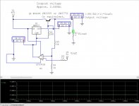
Here is my variation of the circuit I posted a link to in post #30.
I have this circuit working only I have it on a 25.25V supply as of right now.
By adding a 5Vref (LT1021-5) and an opamp (LT1001) and three resistors, I have solved the load and line regulation issue 's.
I am able to pull 4.44A at any voltage below 14V without any voltage droop what so ever.
This is only limited because of the small transformer that I am currently using.
I have my highest voltage setting set for 24Vdc but as long as the transformer can supply the current in to the load it shows no voltage droop or fluctuations as expected when the load is applied and disconnected repeatedly
I did a simulation of the second circuit I posted in post #34.
It does show good load regulation but fails at line regulation.
If the input voltage fluctuates at all, then the output voltage will as well.
Also the resistors in the series pass transistor section need tweaking in order to get good performance at higher currents.
I am not even going to pursue that circuit as this one is showing me super performance and with less parts.
The LT1021 I am using is good for up to 40Vdc in and the LT1001 is good for up to 44Vdc.
Even though this is less than the OP's target voltage of 45V max there are ways around this by using simple resistor voltage dividers.
One can be used on the Vref LT1021 to lower its input voltage or a simpler Vref can be made as well out of a simple resistor and a zener diode.
I just happened to have an LT1021 in my parts bin and I wanted my bench supply to be very low noise and precision as well as drift free.
For a higher input voltage operation a resistor divider can also be used to raise the V- pin of the opamp higher above ground as well.
This will satisfy the 44v power supply maximum of the LT1001 too.
Or you can use a higher voltage type opamp such as the LTC2057HV, LTC6090 or Analog Devices ADA4700-1.
Whatever opamp you do choose to use keep in mind that most opamp's cannot go fully to the rail and this could limit your highest (and lowest) voltage settings.
Especially if this factor is more than the dropout voltage of the regulator circuit.
Depending on the conditions this shouldn't be to much of an issue, but do try to use a Rail to rail type for the widest rage if it is to be adjustable.
As it is it, currently it only goes as low as 1.55v.
Going down to 0V output will require using a true V- on the opamp of at least -2 to -5v below ground.
This is technique is explained in the LMx17 datasheet and app. notes.
Originally I was getting as low .825v out of it, but again it is higher now because the LT1001 is not a Rail to Rail type of opamp and cannot get any lower than it does.
This part of its performance was even worse when I swapped the LT1001 out for a LT1007 type as well.
I will be employing this technique in my bench supply version so that it does go all of the way to 0v, as it will produce 4.44A even at 1.5v!!
But, It is not actually necessary for this particular application.
The circuit I am presenting here, I have running.
I will show a final version for the OP's projected input voltage 45Vdc as the transformers that I have are 35Vac types and produce 49.5Vdc and will satisfy the OP's requirements.
This a great little circuit and it has cost me nothing to build as all of the parts came out of my junk bin pretty much except for the LT1001 and LT1021 that I got as samples from LT.
Cheers !!
jer 🙂
Attachments
- Status
- Not open for further replies.
- Home
- Amplifiers
- Chip Amps
- Lm3886 problem