All of the rest of the grounds in the circuit are connected to the same ground as PIN 7 via your star ground system or whatever.
There are many many threads on this discussion.
And how you set this up can have a great effect on the performance of the amplifier or even cause it to oscillate as well.
Ground loops is another issue as well.
But as far as the connection go that is basically it in the previous post.
Meanwhile,
I have been working on some spice models of the regulator circuit as well.
I found some interesting things to show but I don't have all of my data together yet
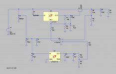
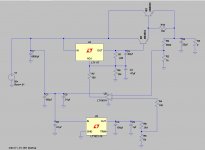
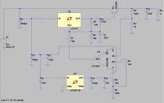
But I do have the asc file to post for any of those whom wish to play with the low voltage version I have made so far.
BenchSupply1 has an LT317 (LM317) in it and it is not found in the earlier version I was using as it was only found after I did an update.
You can put a LT1117 in its place and the circuit simulates fine if you are using an older version of LTspice.
In the Benchsupply2 file I do use an LT1117 as well as I had reverted back to the version I was using before the update.
This second version also has a darlington output configuration as well.
This solves an issue with the LM317's non-linear current limiting problem I mentioned before.
As the output current of the whole regulator gets up to and exceeds about 8 to 10 amps or so, it shuts down the voltage like you had described.
I will describe this in more detail once I get all of my data organized.
I have also included Third asc that I did to see how the LTC2057HV opamp performs and it seems just fine and it uses a LT317as well.
This is when I discovered the current limiting issue and did BS2.
And this was also when I reverted back to the earlier version I have thinking something went wrong with the update.
More on this later. 😉
jer 🙂
There are many many threads on this discussion.
And how you set this up can have a great effect on the performance of the amplifier or even cause it to oscillate as well.
Ground loops is another issue as well.
But as far as the connection go that is basically it in the previous post.
Meanwhile,
I have been working on some spice models of the regulator circuit as well.
I found some interesting things to show but I don't have all of my data together yet
But I do have the asc file to post for any of those whom wish to play with the low voltage version I have made so far.
BenchSupply1 has an LT317 (LM317) in it and it is not found in the earlier version I was using as it was only found after I did an update.
You can put a LT1117 in its place and the circuit simulates fine if you are using an older version of LTspice.
In the Benchsupply2 file I do use an LT1117 as well as I had reverted back to the version I was using before the update.
This second version also has a darlington output configuration as well.
This solves an issue with the LM317's non-linear current limiting problem I mentioned before.
As the output current of the whole regulator gets up to and exceeds about 8 to 10 amps or so, it shuts down the voltage like you had described.
I will describe this in more detail once I get all of my data organized.
I have also included Third asc that I did to see how the LTC2057HV opamp performs and it seems just fine and it uses a LT317as well.
This is when I discovered the current limiting issue and did BS2.
And this was also when I reverted back to the earlier version I have thinking something went wrong with the update.
More on this later. 😉
jer 🙂
Attachments
Oh Okay, that was probably this thread,
http://www.diyaudio.com/forums/chip-amps/252436-lm3886-pcb-vs-point-point-data.html#post3845470
And,
http://www.neurochrome.com/audio/?page_id=941
jer 🙂
http://www.diyaudio.com/forums/chip-amps/252436-lm3886-pcb-vs-point-point-data.html#post3845470
And,
http://www.neurochrome.com/audio/?page_id=941
jer 🙂
Last edited:
Oh Okay, that was probably this thread,
http://www.diyaudio.com/forums/chip-amps/252436-lm3886-pcb-vs-point-point-data.html#post3845470
And,
Neurochrome.com : : Audio : Taming the LM3886 Chip Amplifier
jer 🙂
Thanks, and nice job on the regulator circuits. I think I'm going to give up on mine as I blew my transistors and blew the other 2 after I placed my order.
Because I only intend on dropping a few volts per rail, I think I'm going to just use some 6a6 diodes in series to drop the voltage. Might not be pretty but should work.
Cool, That'll work.
I did that on my variable HV bias supply to power the opamp's in it.
I didn't need to waste a LM78xx and a LM79xx just for Two little opamps.
However, I do intend to Finish these regulators sometime as I do have some very large transformers that I would like too put to use that are in the 40 to 60 volt range.
I am just curious as to what caused your transistors to go out though?!!!!
jer 🙂
Cool, That'll work.
I did that on my variable HV bias supply to power the opamp's in it.
I didn't need to waste a LM78xx and a LM79xx just for Two little opamps.
However, I do intend to Finish these regulators sometime as I do have some very large transformers that I would like too put to use that are in the 40 to 60 volt range.
I am just curious as to what caused your transistors to go out though?!!!!
jer 🙂
Well the first 2 were because I made the rookie mistake of connecting things backwards. But the second time I'm not quite sure. The amp had worked previously but there could have been a short. it was very odd.
I have the parts in the mail, and I'm making a PCB using ultiboard now, that's why I asked about the ground situation. On the bread board, I have the grounds connected together and using that as I would a normal ground for every component.
I got the power supply working, I reduced the volts slightly. I also got one chip soldered in and working. Having some issues with the mute though. I had pin 8 with the switch connected to pin 4, and when I closed the switch the volume slowly reduced until it finally muted. Disconnected pin 8 from 4 and directly to -Ve and mutes not working at all now..
If you have the mute circuit as it is on the application schematic then it may be possible that when you open the switch it provides no path for the voltage on the capacitor to discharge through and it is still holding its charge not allowing the amp to go into mute mode.
If you connected the mute pin directly to -V with out a resistor then it is possible that you have caused too current to flow through the mute pin and/or damaged internal diodes in/or that part of the circuit.
jer 🙂
If you connected the mute pin directly to -V with out a resistor then it is possible that you have caused too current to flow through the mute pin and/or damaged internal diodes in/or that part of the circuit.
jer 🙂
Last edited:
If you have the mute circuit as it is on the application schematic then it may be possible that when you open the switch it provides no path for the voltage on the capacitor to discharge through and it is still holding its charge not allowing the amp to go into mute mode.
If you connected the mute pin directly to -V with out a resistor then it is possible that you have caused too current to flow through the mute pin and/or damaged internal diodes in/or that part of the circuit.
jer 🙂
I originally had it plugged straight in at pin 4.
I do have the 10k resistor and 100uf cap coming off pin 8, but I wasn't sure of how I should connect it. If you look at the schematic, there's a few ways you could interpret that connection.
I was thinking maybe connect it to the input decoupling cap that is first to receive the -Ve, because they share that connection point.
So I reconnected it and basically the same issue. It takes a while to mute. I'm using the recommended 100uf so I wonder why the slow time to mute/ cap discharging.
Lower the value of the cap and it won't take as long, 100uf seems a bit large.
The charge time is set by the value of the resistor and the value capacitor.
You can lower the value of the resistor as well to decrease the charging time as long as you don't lower it to the point of where it exceeds the maximum current flow into the mute pin 4 as specified by the data sheet.
I have read about the mute circuit getting damaged if no resistor is used and is why I had mentioned it in my last post, but I don't l know exactly what is the lowest value that you can use.
I do know that you can remove the cap altogether as well but if the resistor has to high of a value then not enough current will flow through the resistor to the mute section and the amp will then stay muted.
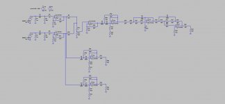
See Figure's 44 & 45 on page 15 & 16 of the data sheet.
jer 🙂
P.S. This is picture is a capture of page 8 of the data sheet. 😉
The charge time is set by the value of the resistor and the value capacitor.
You can lower the value of the resistor as well to decrease the charging time as long as you don't lower it to the point of where it exceeds the maximum current flow into the mute pin 4 as specified by the data sheet.
I have read about the mute circuit getting damaged if no resistor is used and is why I had mentioned it in my last post, but I don't l know exactly what is the lowest value that you can use.
I do know that you can remove the cap altogether as well but if the resistor has to high of a value then not enough current will flow through the resistor to the mute section and the amp will then stay muted.
See Figure's 44 & 45 on page 15 & 16 of the data sheet.
jer 🙂
P.S. This is picture is a capture of page 8 of the data sheet. 😉
Attachments

Last edited:
The graph for mute current stops at 10mA.
I have assumed that is the maximum current that is allowed.
Looking at the mute circuit you can see that this current passes through two 1k0 resistors.
10mA of mute current through a 1k0 resistor requires it to dissipate 100mW. That is a lot for an IC resistor.
This will determine the lowest value mute resistor when supply is at absolute maximum for the transformer being used.
The graph for mute current stops at 10mA.
I have assumed that is the maximum current that is allowed.
Looking at the mute circuit you can see that this current passes through two 1k0 resistors.
10mA of mute current through a 1k0 resistor requires it to dissipate 100mW. That is a lot for an IC resistor.
This will determine the lowest value mute resistor when supply is at absolute maximum for the transformer being used.
What do you mean 2 10k resistors? The datasheet only calls for one coming off pin 8.
I said 1k0
Look at the datasheet. There are two 1k0 resistors feeding the mute current to the mute pin.
Look at the datasheet. There are two 1k0 resistors feeding the mute current to the mute pin.
Andrew is referring to the equivalent circuit schematic for the LM3886 shown on Page 7 of the data sheet.
There is absolutely no advantage of increasing Imute beyond 500 uA. I describe how the mute circuit works on my Taming the LM3886 page.
I recommend that you select Rmute to ensure that you have Imute = 500 uA under the worst case operating conditions. This will ensure that the LM3886 un-mutes when the supply rails are as close to their target values as possible.
~Tom
Hey Gerald, is there a way to add a subwoofer circuit, basically adding a third chip to my project. There's only two inputs L and R, so besides running a wire from either of the two channels is there another way?
Use an MFB filter with two inputs.
This ADDS the two Left and Right signals AND attenuates the medium and high frequency content to feed a Bass only Power Amplifier.
Just one opamp in the circuit.
Add an adjustment pot to the MFB gain to reduce the bass signal to the amplifier to suit your main channels. Alternatively add an adjustment pot after the filter and then another opamp (the second half of a dual) to buffer the signal being sent to the Power Amplifier.
Yes, There are many examples here,
https://www.google.com/search?q=sub...qCtG3yASlmIHQCQ&ved=0CFIQsAQ&biw=1024&bih=678
https://www.google.com/search?num=1....12.0....0...1c.1.56.hp..0.19.875.n2EmE3ZobC0
Basically as Andrew mentioned you have a simple two channel mixer to combine the L & R signals then run that though a Low pass filter of your choice and then on to another amplifier unit.
It can be done with a single or a dual opamp, there is no harm in using a dual since most decent quality opamp chips are dual's anyhow.
Here is one example as such,
http://www.circuitstoday.com/low-pass-filter-for-subwoofer
You can also chose to have a stereo sub setup if you prefer depending upon your needs.
Just make sure that what ever you are using to drop the voltage on your power supply, whether it is a regulator or Diodes, that it can handle the added extra current from adding the subwoofer amplifier section or sections.
Also you will need a suitable Regulator for the opamp's as well since most are only rated to +- 18v max some do go as high as +- 22v and some are actually only rated for 15V as +-15v is the norm anyhow.
If you are using the same setup then the LM317HV's will work nicely and you just have to calculate the proper resistor values for 15v is all.
There are also some more fine examples of Filters, EQ's and Crossovers over on Rod Elliott's ESP site as well.
ESP Projects Pages - DIY Audio and Electronics
jer 🙂
Last edited:
One other option I didn't mention is that if you are using a toroid type power transformer it is possible to unwind a few turns from the secondary to drop your output voltage as well.
jer 🙂
Even easier is to add an anti-phase winding.
i.e. a winding that when connected reduces the transformer output voltage.
- Status
- Not open for further replies.
- Home
- Amplifiers
- Chip Amps
- Lm3886 problem