Referencing the original post, I've been following this thread with interest, and look forward to step h), you can count me as one of "those interested" in the eventual PC Board order, once the design has been fully baked. For the time being though, I will continue as an observer, since this type of design is not really my skill set.
Last edited:
Referencing the original post, I've been following this thread with interest, and look forward to step h), you can count me as one of "those interested" in the eventual PC Board order, once the design has been fully baked. For the time being though, I will continue as an observer, since this type of design is not really my skill set.
We are still alive! For the time being I am building a triple-parallel LM1875 power block. palstanturhin has already done experiments with the controlling OP-AMP in a composite amplifier configuration and rather quick experiments indicate fine results. Chris has done experiments with connecting LM1875 in parallel, which can cause unforeseen dynamic effects such as oscillation. We have all experimented with the stability of LM1875 and TDA2050, both genuine and fake.
The work on the stability of LM1875/TDA2050, alone and in parallel, is like designing the foundation for a house - if you make a mistake there, you cannot compensate sufficiently in the further design.
The power part has to be fully predictable and reasonably suited. If the power part is not predictable and for instance starts oscillating, the OP-AMP cannot do its job. The parallel amplifier chips have to share the load well or we risk an avalanche effect. This is why we are so careful with this first part.
Makes good sense to me, I actually read through the whole thread starting from post 1, and I've enjoyed reading the thought and design process. I also read the Radio Electronics article, so I'm up to speed on what's going on. I just don't have a lot to contribute technically, since I'm not experienced with Op-amp circuit design.
At first I wondered why you were bothering with a 30 year old IC when the LM3886 exists, but after reading more about the LM1875, it appears to have a lot of followers.
If I could add one request, it would be to include a design for a CLC filter (perhaps on a small board), at the power entrance, to remove residual switch mode power supply ripple. I think the option of using a pair of 24V switch mode supplies would be a natural fit for this project, eliminating the heavy toroid and large filter capacitors.
Hi, just a hint from practice with conventional transformers: If you want to include a fuse in the secondary side of your power supply, make the disadvantage of the voltage drop an advantage.
Past the rectifier, place 1/2 of your capacitors, than the fuse and finally the second half of your capacitors.
What you get is a CRC power supply with better ripple rejection, but without additional voltage drop from a resistor, as any fuse is one.
The fuses will not blow when you turn on the power, as the high inrush current is absorbed by the first row of capacitors. Maybe do not use a "fast" fuse.
I prefer to use CLC configurations, the ripple is smoothed out under load, much better than ton´s of capacitors or a CRC design. An old principle from valve amps, where high voltage capacitors where extremely expensive. The inductor between two capacitors makes the output voltage free from "hard" ripple.
If you watch it on an oscilloscope under load, it is really impressive how different the voltages look before and after the inductor coil.
PS most SMPS have such an CLC integrated anyway, but a second stage can only improve the output.
Last edited:
Neurochrome offers top-performance with LM3886 but DIY only on board-level.
Fremen also uses LM3886 if I'm not wrong.
There is another high-level LM3886/LME49710 project going on.
So we started in the other end - how to build a very cheap but well performing amplifier with a very limited budget. If you understand the principles of a composite amplifier, you can take almost any chip-amp (preferably one that can operate from a symmetrical supply) and a cheap OP-AMP and make a really well sounding amplifier. It need not be a well performing TI chip, almost any brand will do for a good result.
Then, less experienced members can experiment with making their own designs.
If anyone like to continue with power supplies, we can start such projects when this one is at its end. Linear power supplies are generally much easier to design that many believe. It is also about understanding the basic principles and then you can go on yourself.
Constructing more complex SMPS is difficult because it requires special components and sometimes particular test gear.
We can also discuss CLC-filter design which I rarely use for reasons I can explain then.
I learned electronics the wrong way by being taught a lot of mathematics by very skilled teachers who could not construct much practical electronics themselves. I learned to make practical electronic constructions through stubbornness and a lot of practical help and advice from technicians and engineers with a more practical education.
On this forum we have all kind of members. Those with little experience but some interest. Some of the top-dogs from they golden days of electronics in US and Europe. Some who have the skills to make almost anything work, some who knows how to evaluate audio constructions and some who knows so advanced theory that I often get lost.
If anyone has an interest in electronic construction, it is possible to learn how to make more simple constructions even without a technical background. Patience is enough.
Last edited:
I was thinking more about using commercial switch mode power supplies, like the meanwell ones which neurochrome recommends, and use a small LC filter to get rid of the tiny bit of leftover ripple. I wouldn't try to do a switch mode supply from scratch, it is possible to buy very nice ones for very reasonable prices, and they are not easy to design well.
Anyway I am following this thread with interest!
Anyway I am following this thread with interest!
I was thinking more about using commercial switch mode power supplies, like the meanwell ones which neurochrome recommends, and use a small LC filter to get rid of the tiny bit of leftover ripple. I wouldn't try to do a switch mode supply from scratch, it is possible to buy very nice ones for very reasonable prices, and they are not easy to design well.
Anyway I am following this thread with interest!
You are right, it is possible to buy a good Meanwell power supply for a decent price. One issue with Meanwell power supplies is that most are single voltage which Neurochrome may use for the large BTL-coupled version. Do you know if Neurochrome also recommends Meanwell when a symmetrical supply voltage is needed?
fdenys bought an SMPS (+/- 24V) particularly suited for amplifier use. He seems very happy with this SMPS.
Yes, an LC filter can reduce output ripple from an SMPS. But, an LC filter can also start ringing such that you end up having a higher level of voltage swings. Then, you need to dampen the LC-filter and the filter becomes less efficient as the result. For me filters, such as LC filters, can be necessary and I will implement what is needed. If not needed, I will not just add an LC filter as an extra safety against ripple because the end-result may be worse.
Yes, I see Tom (Neurochrome) is using a pair of MeanWell 24V power supplies in a couple of his designs. He even has designed a control board to facilitate synchronized start up of two individual supplies, so that the LM3886 does not latch up.
I am presently building a preamplifier which uses a MeanWell split 15V supply, and am impressed by its performance (absolute silence on a moving coil preamplifier), hence my attraction to the brand for possible use in a power supply. The designer of my preamp used an input filter using small value inductors, and a few capacitors, as well as load resistors, to slightly reduce the noise coming from the supply. Neurochrome appears to have a similar design with his power supply board, and since both him and the designer of my preamp are former IC designers for big name semiconductor companies, I am thinking it's a good idea for me to pay attention to their design choices.
I have previously purchased an eBay power supply with limited success, the one I am presently using has excessive noise on the output. I addition to this, it does not carry the approval of the CSA, or UL, or CE marking, which makes me suspicious about the isolation between line and load, and also about how well protected it is. I tend to leave equipment going for hours when I'm out of the room, so safety is something of a concern. That said, if there is a specific eBay supply that has been documented to work well, I'm game!
I understand that a linear supply works well, I just think it would be fun to try combining a composite amplifier design with trying to use a switch mode power supply in an amplifier. Partly because they are light, and partly because... well, I've built lots of linear supplies before, and it's fun to do things I've never done before.
About ringing, usually for tube amplifier design I simulate this using PSUD-II, and you're right, it can be absolutely terrible for CLC supplies. I have never tried a similar simulation for any frequency besides 60Hz though, and I never considered this could be an issue!
Thanks for the explanation.
Neurochrome uses stacked single voltage Meanwell supplies to generate symmetrical voltages. Meanwell is known to be reliable.
Indeed, seek inspiration about filters from other competent designs. For a pre-amp, filter ringing is less of a problem because the current consumption is pretty stable. Tom should know what he is doing with his filters.
Fire safety approval is very important if you leave your gear ON when you are not in the room. Isolation, I would be less worried about because the need is so trivial and proper solutions known for decades. Use of cheap components increase the risk of overheating.
An SMPS is probably a very good choice for the composite amplifier we try to construct. A priori I will prefer a single SMPS with symmetrical output, perhaps the one fdenys is using.
The risk of ringing depends fully on the load. With a dynamic load, such as a power amplifier, you may have ringing.
The inductors I am taking about are tiny, mostly to deal with the tiny bit of ultrasonic hash on the output of a quality switch mode supply. Certainly not the large inductors used to filter 120Hz ripple, I have seen supplies with poor damping respond badly to transients, and since this is a class AB amplifier the transients will be substantial, making ringing very likely if we use badly chosen inductors and filter capacitors.
For isolation I agree that it is trivial in a good design but point to the Chinese cell phone charges which have shocked people due to inadequate isolation between line and load. There are established product standards which are required to achieve a CSA listing, and it is obvious many of the cheap eBay boards do not follow these guidelines. Not to be a nerd about it, if there is a good one I'm game to try.
Fire risk is somewhat mitigated by proper fusing and an all metal enclosure.
If you do decide on using a SMPS in the final design, I will probably just order the same one. One thing I learned from the preamp design, is putting the SMPS in a separated metal compartment within the chassis is a good idea noise wise.
You could fool around a little bit more with this circuit. Change the gain of the 1875 to -3.5x, and see what you can get out of it?
Lets forget high gain at the 5534 stage also, if needed. We may be forced to use a preamplifier.
Minimum gain without oscillations at the negative channel seems to be -3x at the 1875.
FF's wild guess -3.5x was quite accurate.
I am not able to filter out all the ripple with less gain.
So, FF, when you build your parallel proto, use -3.5x gain.
lme49990 x lm1875...off topic ? «AMPLIS LM1875 MONO STEREO BRIDGE - Page 18» - 30075848 - sur le forum «Amplis et Préamplis» - 1056 - du site Homecinema-fr.com got one board and parts to mount...
FF, I have posted in 2016 this circuit as enhanced My Ref . The sound of this amp is very particular. As you see the opamp can load several Holloway amps which can be paralleled . I can replace the LM3886 by 1875 if you want.
Kokoriantz,
I heard the two music pieces on YouTube and you are right, they sound very fine though I assume YouTube use compression.
This composite amplifier I suggest is left using LM3886. LM3886 has the advantage that one is sufficiently powerful alone (no need to put more in parallel). As I can see, the LM3886 is used in a coupling with both negative and positive feedback. That means the transfer function is (much) more complex to understand. It may be a very relevant option for later.
A first version of our composite amplifier should be straight forward such that it is easy to understand, easy to test and easy to modify. The experiments done by palstanturhin indicate that as a first version we can use a power part which is DC coupled and linear until the bandwidth limitation. That means, even persons without an oscilloscope can design and test the power part statically with a DDM. Then, the power part can be used with an outer controlling loop that for a start can be left DC-coupled as well and tested statically with a DMM. In the end, the input can be AC-coupled.
If the power part is configured so simple as a linear inverting or non-inverting amplifier, most can experiment with own designs around this concept.
The LM3886 is an obvious candidate for future versions.
You could fool around a little bit more with this circuit. Change the gain of the 1875 to -3.5x, and see what you can get out of it?
Lets forget high gain at the 5534 stage also, if needed. We may be forced to use a preamplifier.
Minimum gain without oscillations at the negative channel seems to be -3x at the 1875.
FF's wild guess -3.5x was quite accurate.
I am not able to filter out all the ripple with less gain.
So, FF, when you build your parallel proto, use -3.5x gain.
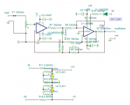
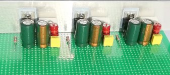
The gain will be -3.5x. Though I understand if you start doubting how much work I in reality do, there is actually some progress (see below).
I use low impedance connections as mentioned by Turbowatch2 and Kokoriants. This way I should have no new oscillation effects. Adding the low impedance lines (power, ground and output) took me quite some time.
I hope finishing tomorrow evening.
Test should be from Monday-Tuesday. If the LM1875s just don't fight with one another, I can soon continue with the OP-AMP part.
Testing will be low-risk first.
Attachments
Last edited:
lme49990 x lm1875...off topic ? «AMPLIS LM1875 MONO STEREO BRIDGE - Page 18» - 30075848 - sur le forum «Amplis et Préamplis» - 1056 - du site Homecinema-fr.com got one board and parts to mount...
Not at all off topic. Another composite LM1875 amplifier.
Am I right that R6 and R7 are connected? R6 serves to reduce the LM1875 gain?
Let's hear your experience when ready.
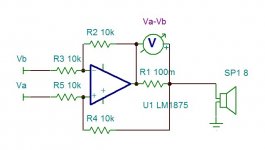
Holloway
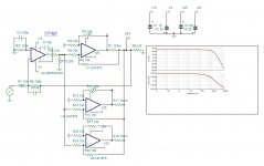
The Holloway circuit is very simple . The differential voltage of the inputs find it's way across the weighing resistor R1. By this the amplifier outputs a current equal to (Va-Vb)/R1. The load sees the output impedance as 20k.
Here what it gives with triple LM1875 .
The compression on the YouTube is not a matter of MP3, it is due to AGC of the recorder.
Attachments
Last edited:
Holloway:
Looks like a differential amplifier? How tight matching between resistors does that require to make it work in parallel mode?
Looks like a differential amplifier? How tight matching between resistors does that require to make it work in parallel mode?
- Home
- Amplifiers
- Chip Amps
- LM1875 in parallel configuration and used in a composite amplifier.