Abbado II has at last gone out to JLC to have them build some - this updated version ditches the CJ431s in favour of IRLED fed regulation for the DAC chips. The factory fitted components are shown on the PCB above. Once we get boards back I'll select and solder the filter caps (which need to be close tolerance hence can't be done at JLC), wind some inductors and then after testing a pair, kits will be available.
Since Abbado II runs on 9V its eminently suited to being powered by battery, I plan to check out how it fares fed from a couple of 18650s.

Here's the first stuffed board back from JLC and its playing music. 😎 Gotta get to work on the BOM now, there's the odd fact that JLC don't have 39ohm 0805 resistors for some obscure reason so some minor re-design is called for....

The commercial thread for Abbado II has now gone live : https://www.diyaudio.com/community/threads/abbado-ii-nos-dac-kits.400326/latest
For those for whom 16 paralleled DAC chips isn't quite enough, I've stacked some extra chips over the top of the first layer on one of my later prototype Abbados. Its fiddly straightening out the legs of the 1545s and bending them to fit snugly over the top of some of the existing DACs but eventually I got a 24 chip version of Abbado running. There's no particular reason to stop at 8 extra chips except I wanted to check there's enough headroom in the design to tweak it up further. The max output level has gone up from 1.3V to 1.8V and total current consumption from 200mA to 240mA. I haven't listened yet but its showing clean output at these levels on the 'scope.

I soldered the new chips at the ends of the lines of chips - top and bottom of the pic - nearest the decouplers. The pin7 bias needs increasing too (solder an extra 0805 11k on top of the existing one) or the extra output current will remain as potential only. Compared to 1387s, the 1545s do run noticeably cooler.
I've yet to figure out what the practical boundary of the design is going to be, 32 chips isn't the upper-most limit but stacking DACs more than 2 high is only for the hair shirt guys methinks 🤣
Not just to increase the voltage output Pete, no, that's just a side effect. The point is to improve the SNR by averaging (summing) more signals.
I see you sent me a package Richard. Thank you.
A question about input signal hook up. I only use a USB output from a cellphone to drive the digital signal to my current DACs (no computer hookups). What do I need to do connect a USB input to your board? I know you've explained this somewhere but I'm not really oriented with Is2 and all that stuff.
Sorry for the ignorant type question.
Pete
To go from cellphone USB to I2S one of the USB1.0 style adapter boards would be the thing to have. PCM2706 is one chip that does the deed : https://www.aliexpress.com/item/4000141799137.html. Note on this module there are 4 wires carrying signals but only 3 are needed for the I2S interface to the Abbado, SCK isn't used.
The PCM2706 based board finally arrived so now I can get on with building out the Abbado II DAC. Now just to find time with all the normal summer outside-the-house repairs..
Hi Richard, I'd just like to check the connections on your above listed PCM2706-based USB to Is2 board. The card itself is powered by the USB connection to my cellphone, correct? I'm connecting your DAC board to the "A" set of connections, correct? As you said SCK is not used nor will I be using the 5V output connection? The GND is still used to your board (and possibly to ground the RCA outputs (-) terminals)? What are the set of "B" connections used for??? I received zero documentation with this board.
Thanks, Pete
Thanks, Pete
Attachments
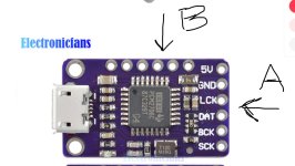
Hi Pete - I haven't a clue what the 'B' pins are connected to, you might gain insight if you eyeball the applications section of the PCM2706 datasheet. For example it might support stuff like volume up/down, track skip and the like with switches to those pins. You're right its those 'A' connections, you have no need of the '5V', but you will need 'GND' and yes its powered by your phone.
The PCM2706 has an onboard dac. Among the pins that run along the top are the analogue outputs of said dac. See the datasheet for more details.
https://www.aliexpress.com/item/400...8819527&spm=a2g0o.ppclist.product.mainProduct
https://www.aliexpress.com/item/400...8819527&spm=a2g0o.ppclist.product.mainProduct
Please could you explain difference between those DAC's?
lingDAC - cost effective RBCD multibit DAC design
Kubelik NOS DAC kits
Also there is no words about sonic experience and comparison with Sigma DAC's.
lingDAC - cost effective RBCD multibit DAC design
Kubelik NOS DAC kits
Also there is no words about sonic experience and comparison with Sigma DAC's.
You're asking about Phi DecaDAC in comparison with Kubelik.Please could you explain difference between those DAC's?
Simply put, DecaDAC has more paralleled DAC chips (10 vs 6) and as a result, a lower noisefloor. It has a much more complex LC filter (7th order vs 3rd order for Kubelik) which gives improved dynamics and cleans up the higher frequencies subjectively.
I don't have any comparisons of recent DAC designs against S-D type DACs but I wrote a comparison of my lingDAC against PCM5102 in 2017 on Hackaday : https://hackaday.io/project/27001/log/71059-how-to-give-my-listening-impressions.
How to order DecaDAC? How much it cost? Do I need to solder some elements? Is something missing to complete dac?
Thanks
Mario
Thanks
Mario
As DecaDAC is a very old design I'm not sure that we have any kits left, I'll need to check. You can find details here : https://www.diyaudio.com/community/threads/phidac-hex-kits-with-pre-built-filters.354799/
The most recent of my DAC kits is here, Abbado II, which I'd recommend rather than DecaDAC : https://www.diyaudio.com/community/threads/abbado-ii-nos-dac-kits.400326/latest
The most recent of my DAC kits is here, Abbado II, which I'd recommend rather than DecaDAC : https://www.diyaudio.com/community/threads/abbado-ii-nos-dac-kits.400326/latest
Hello Abraxalito,
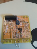
Working on a new project, I'm moving on with PhiDAC kits I had bought many years ago. I have 2 power supply boards (see picture) and I wonder how many PhiDAC each power supply board could drive (1 ?2? 3 boards ? or more?).
Also, from what I remember, you can arrange 2xPhiDAC boards to get balanced outputs. How to do that ? How to interconnect the boards? How to use the small switch and how to power the boards? This is not anymore clear to be. I would be super interested by a link to an explanation, or a small drawing.
The idea is to use the PhiDACs in a USB to multi channel set-up.
Best regards,
JMF
Attachments
- Home
- Source & Line
- Digital Line Level
- lingDAC - cost effective RBCD multibit DAC design