Built Celibidache now available to order
Here's the Vendor's Bazaar thread : https://www.diyaudio.com/forums/vendor-s-bazaar/379964-celibidache-nos-dac-new-post.html
Kits will be along in a few weeks once I've gathered more data on the variability of the design and we've stocked up on the needed parts.
Here's the Vendor's Bazaar thread : https://www.diyaudio.com/forums/vendor-s-bazaar/379964-celibidache-nos-dac-new-post.html
Kits will be along in a few weeks once I've gathered more data on the variability of the design and we've stocked up on the needed parts.
Testing DACs
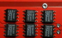
I've been trying to get to the bottom of the variability in full-scale output voltage between builds of the Celibidache and so decided to test a few hundred chips to see what the production spread looks like. The result is - pretty much exactly as the TDA1387 datasheet says. It says there's +/-14% variation on a nominal 1mA, I found ~26% between top and bottom with my sample of ~500 chips (counted by weight). And about 2% are dead ones.
What's most interesting to me is there is clearly correlation between the markings and the full-scale output current. There are two kinds of markings making up the vast majority of the chips I have, shown in the second pic below. The marking style at the top occupy the bottom end of the distribution - I found none of that style in the highest output current bin. And vice-versa, the bottom style I found only 2 of in the lowest current bin (I created 4 bins). Whether maximum output current is correlated with SQ I don't yet know, some listening will be required.
Attachments
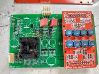
Progress towards Celibidache kits - the machine loaded boards turned up today. Due to JLC's pricing structure we've gone for green in this instance.
Looks promising.
Warming up the iron for the new year's DAC adventure
Merry Christmas to You two
George
Warming up the iron for the new year's DAC adventure
Merry Christmas to You two
George
Jim - wifey had some JLC coupons to use up on this one, we bought 10 off and the price was 200rmb. So around $3 each in quantity 10. But without coupons you can probably add 50%.
Wow....bargain. Will you be sharing the smd population files for fab shop. ?
I fully understand if not.!
I fully understand if not.!
I'm not averse to sharing data, just thinking out loud where it would lead. With an SMD population file I figure there'd be a need for further support (if I'm wrong on that then please point out my error) and I'm not inclined to give such support when it would appear to cannibalize kit sales.
Yes I fully understand Richard. Sometimes it takes me while to grasp what maybe a 'commercial' project or not. !
If you're after the least 'commercial' project then I reckon Kubelik would be it, there's a BOM (with Mouser part numbers), gerbers and build guide. So far though no-one's done it to my knowledge, the nearest would be @Vunce but last time I asked he had other projects lined up prior to Kubelik.
Oh - and thanks for all your Xmas wishes guys.
Oh - and thanks for all your Xmas wishes guys.

Hey abraxalito! My two kits came and I got one together! What an exciting way to spend new years eve hahaha.
The only thing I mucked up was soldering resistors where the ferret beads went for the left channel. I debugged it and everything else went smoothly.

Going to finish the other board, flip the phase on it, and have a balanced build. After that I'm planning on putting it in a nice little box with a raspberry pi and have a sweet network streamer with balanced out.
Really cool project.
The only thing I mucked up was soldering resistors where the ferret beads went for the left channel. I debugged it and everything else went smoothly.
Going to finish the other board, flip the phase on it, and have a balanced build. After that I'm planning on putting it in a nice little box with a raspberry pi and have a sweet network streamer with balanced out.
Really cool project.
Also, this is by far the most smd components I've hand soldered at one time haha. Thanks for including extras of just about everything, they came in handy as more than one resistor flew off my tweezers as I was about to lay it down. Where those resistors landed, god only knows.
Excellent work! So I wasn't the only one at my bench on New Years then? I too wonder where all those 'escaped' resistors go, there must be dozens of them around my workplace! I know many of them fall into my computer keyboard, sometimes the keys get stuck due to 0805 parts falling beneath them and I periodically need to clean it out.
- Home
- Source & Line
- Digital Line Level
- lingDAC - cost effective RBCD multibit DAC design