I found this tidbit in this link WRT the WE 119: https://www.onallbands.com/wp-content/uploads/2019/08/Non-LinearXformerBehavior.pdf
200V P-P is around +39 dBu.
If the "goal" is not to LF saturate but shave off some HF "edge," then it's unlikely you'll need ridiculous elevated levels.
Even with 200V PP applied, the maximum output of the BOP 100-1M amplifier, the 119C's B-H curve shows no signs of saturation. The ellipse is certainly not symmetrical, but it's not saturated.
200V P-P is around +39 dBu.
If the "goal" is not to LF saturate but shave off some HF "edge," then it's unlikely you'll need ridiculous elevated levels.

Yeah I don't think I was clear enough throughout all this. I will be using this box for subtle "rounding." The rounding I'm talking about is not saturation but a subtle attenuation of harsh midrange and high frequencies. The 111C is only rated for 30-15k (+/- .5 db I think?), So whatever it's doing above 15k is apparent to me.I found this tidbit in this link WRT the WE 119: https://www.onallbands.com/wp-content/uploads/2019/08/Non-LinearXformerBehavior.pdf
200V P-P is around +39 dBu.
If the "goal" is not to LF saturate but shave off some HF "edge," then it's unlikely you'll need ridiculous elevated levels.
Once I get the amp and try some stuff I'll do a bunch of before and after tests. I want to see if I can measure the attenuation I'm talking about. I already know it's doing something, as I posted the null results even at normal mix levels. The question is do you think -65dbfs is something that can be heard. I can hear it, but the average listener prob won't. The difference is not like dither levels... That's super low into the -100s.
We'll see. Even if nothing more really happens with the extra gain I will be happy. Ive learned lot here in the last week, and thank you all for being so involved and helpful.
**Also, my goal throughout all this was just to see what happens with more gain. Period. Often times in analog gear you get different results from driving it harder - I wanted to see what those results would be, if any. Does it provide more of this "rounding" effect? Will I start to hear the low end get weird? Will there be any unexpected effects? It's a mystery and I want to hear for myself.
Last edited:
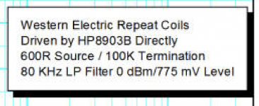
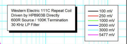
That is the same document I linked in the previous page. I do see where they say the 200V P-P thing but I was under the impression that they used much less power in the actual tests. Here is the legend for each graph. Do those values correspond with what you're saying?I found this tidbit in this link WRT the WE 119: https://www.onallbands.com/wp-content/uploads/2019/08/Non-LinearXformerBehavior.pdf
200V P-P is around +39 dBu.
If the "goal" is not to LF saturate but shave off some HF "edge," then it's unlikely you'll need ridiculous elevated levels.
Looks like the first test was across the entire frequency spectrum and the second was only looking at 30hz (says there was a low pass filter applied). Makes sense since that's the frequency for which the max rating is specified.
Attachments
This is priceless. I need more popcorn 😉I appreciate the help you've provided. Your expertise is in electrical engineering and mine is in audio engineering. Thanks again.
Oh no is he also an audio engineer?? Lol if he is he never really talked about it. Either way I stand by what I've said. Im confident in my audio engineering abilities.This is priceless. I need more popcorn 😉
If you have no clue about these level issues, how can you be any engineer??Oh no is he also an audio engineer?? Lol if he is he never really talked about it. Either way I stand by what I've said. Im confident in my audio engineering abilities.
Not that you probably are a nice guy.
Jan
If you have no clue about these level issues, how can you be any engineer??
You probably are a nice guy, but this may be a case of Kruger-Dunning.
Jan
The levels I need to know about, I know. A mixing engineer just needs to be able to deliver a well balanced mix to the customer. You don't need to know the depths that we've gone here, especially since a lot of audio is mixed "in the box" (digital) nowadays. If you're completely in the box you're really just working with dbfs, which is a much simpler concept. I'm not saying it hurts to know how to gain stage for analog, but it's not necessary when you have 32bit floating point processing in the software - you essentially have infinite headroom.If you have no clue about these level issues, how can you be any engineer??
Not that you probably are a nice guy.
Jan
There are countless mixing masters that don't understand the depths of what we've been talking about in this thread. Understanding dbu/dbm/dbv etc was more necessary when everything was analog. I know some of the basics but have never been in the situation where I was trying to drive levels that are hotter than +26dbu into anything, so this has all been a learning experience. You all have been great so far in terms of being helpful.
Really? Look, I'm busy with actual stuff today, but when I get a second, since that's about all it takes, I'll run a response for you up to 40KHz. But here's a clue: there's no "rounding".Yeah I don't think I was clear enough throughout all this. I will be using this box for subtle "rounding." The rounding I'm talking about is not saturation but a subtle attenuation of harsh midrange and high frequencies. The 111C is only rated for 30-15k (+/- .5 db I think?), So whatever it's doing above 15k is apparent to me.
Listening for the "effect" is an uncontrolled, biased means of evaluation. You'll get the answer you want, just not reality. I've tried to explain that too, but we're in that "I know what I hear" rabbit hole.**Also, my goal throughout all this was just to see what happens with more gain. Period. Often times in analog gear you get different results from driving it harder - I wanted to see what those results would be, if any. Does it provide more of this "rounding" effect? Will I start to hear the low end get weird? Will there be any unexpected effects? It's a mystery and I want to hear for myself.
So, you monitor "in the box" too? You have, what, an AES jack in your head and don't use your ears? Just getting it out of the box to monitors will mean you DON'T have infinite headroom, and 32 bit float becomes 24 bit, or 16 bit fixed point.The levels I need to know about, I know. A mixing engineer just needs to be able to deliver a well balanced mix to the customer. You don't need to know the depths that we've gone here, especially since a lot of audio is mixed "in the box" (digital) nowadays. If you're completely in the box you're really just working with dbfs, which is a much simpler concept. I'm not saying it hurts to know how to gain stage for analog, but it's not necessary when you have 32bit floating point processing in the software - you essentially have infinite headroom.
Still necessary. Especially to know the difference.There are countless mixing masters that don't understand the depths of what we've been talking about in this thread. Understanding dbu/dbm/dbv etc was more necessary when everything was analog.
I haven't said what my expertise or background is.I appreciate the help you've provided. Your expertise is in electrical engineering and mine is in audio engineering. Thanks again.
Yes, but only for 50+ years. But not limited to that either.Oh no is he also an audio engineer??
I don't talk about my background because it feels like massive egotism. I hope people can tell something about my experience based on knowelege shared.Lol if he is he never really talked about it. Either way I stand by what I've said. Im confident in my audio engineering abilities.
There's no point in going back and forth. I don't have anything to prove. All I know is I'm able to make very high quality balanced mixes with the knowledge I have. That is enough for me. Well besides this experimental transformer thing, which I've never done. That is where I needed your guys help, which I'm thankful for. I used to have a cool hybrid system with lots of cool analog gear. I had no problems with my gainstaging there.
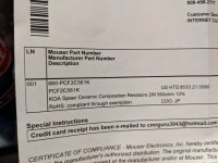
Resistors came in today. Amp comes on Tues. Only thing I'm confused about is whether or not I'm putting these resistors on both the + and - lines before I send them to the 111C or just the +. My guess is just the +.
Also, the 111C secondary is connected as balanced, so it's wired for all 3 pins on the XLR outs. I'm assuming since there won't be a cold signal going into the transformer (since it's just + and ground from the amp) that it doesn't really matter?
Any help is greatly appreciated. Have a good Friday/weekend.
Just in the + side is fine. What resistor value did y get?Resistors came in today. Amp comes on Tues. Only thing I'm confused about is whether or not I'm putting these resistors on both the + and - lines before I send them to the 111C or just the +. My guess is just the +.
We don’t use the therm “cold” in audio. The power guys do.Also, the 111C secondary is connected as balanced, so it's wired for all 3 pins on the XLR outs. I'm assuming since there won't be a cold signal going into the transformer (since it's just + and ground from the amp) that it doesn't really matter?
As to the ground of the XLR, yes it matters. There’s a ground terminal on the 111C, it should be connected there.
Any help is greatly appreciated. Have a good Friday/weekend.
I got the ones you told me to get, KOA Speer Ceramic 2W 560ohm 10%Just in the + side is fine. What resistor value did y get?
We don’t use the therm “cold” in audio. The power guys do.
As to the ground of the XLR, yes it matters. There’s a ground terminal on the 111C, it should be connected there.
When I say cold I mean pin 3, not ground. I already have all the XLR grounds tied to the 111C ground. I'm talking about pin 3. Pin 3 of the Xlr going into the 111C wont be connected, but the one going out of the 111c into the pad/interface will be. Hope I'm making sense
Attachments
An XLR input to a device needs to have a signal between Pin 2 and Pin 3. The secondary of your 111C should be connected between Pin2 and Pin 3. Ground should be connected to the ground lug. If you use a pad, the pad should be a balanced configuration, and its outputs connected to Pin 2 and Pin 3. If you omit, or ground Pin 3 you have eliminated any and all advantages of a balanced input. If you are driving that input from a transformer, and you don't connect Pin 3, but instead, ground one side of the output winding, it will work but you've now created an unbalanced circuit. No idea why you'd do that when a transformer is by nature a balance source.
Note that IF the input to your device is a transformer input, you must either connect the signal between Pin 2 and Pin 3, or from Pin 2 to Ground AND ground Pin 3. It won't work otherwise.
The output of your amp should be connected, through the resistor, to the primary of the transformer. The output appears between the red and black terminals, or if you use the amp in bridged mode, between the two red terminals.
Currently everything is wired in the proper balanced configuration. The pads as well. My question was where does the negative from the amp go - to terminal 7 of the transformer (where pin 3 of the XLR input is connected), or to the ground of the transformer. Both pin 2 and 3 carry an audio signal from the interface, only one is inverted, but the negative output of the amp is just a ground, no? If it is a ground, then shouldnt that go to the ground of the transformer?An XLR input to a device needs to have a signal between Pin 2 and Pin 3. The secondary of your 111C should be connected between Pin2 and Pin 3. Ground should be connected to the ground lug. If you use a pad, the pad should be a balanced configuration, and its outputs connected to Pin 2 and Pin 3. If you omit, or ground Pin 3 you have eliminated any and all advantages of a balanced input. If you are driving that input from a transformer, and you don't connect Pin 3, but instead, ground one side of the output winding, it will work but you've now created an unbalanced circuit. No idea why you'd do that when a transformer is by nature a balance source.
Note that IF the input to your device is a transformer input, you must either connect the signal between Pin 2 and Pin 3, or from Pin 2 to Ground AND ground Pin 3. It won't work otherwise.
The output of your amp should be connected, through the resistor, to the primary of the transformer. The output appears between the red and black terminals, or if you use the amp in bridged mode, between the two red terminals.
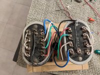
This whole time I have had no idea what terminals on the 111C are the primary and which are the secondary. All I can see on the document is "line" and "drop." That has really been making things confusing to me. I'm gonna try and figure it out.
I wired this thing based on a configuration I got from the headspace forum.
I wired this thing based on a configuration I got from the headspace forum.
**Ok I think I just learned something. A transformer can create a balanced signal from an unbalanced signal? That explains my confusion. I was looking over Marcels schematic and was wondering why the negative of the amp would where the "cold" wire of the XLR input went.
So should I rewire the transformers like Marcel has them? Id still be using just the 560ohm resistors for now..
So should I rewire the transformers like Marcel has them? Id still be using just the 560ohm resistors for now..
And vice-versa.**Ok I think I just learned something. A transformer can create a balanced signal from an unbalanced signal?
Yes, use his schematic.That explains my confusion. I was looking over Marcels schematic and was wondering why the negative of the amp would where the "cold" wire of the XLR input went.
So should I rewire the transformers like Marcel has them? Id still be using just the 560ohm resistors for now..
Primary and secondary are somewhat arbitrary. Usually the "primary" is the winding to which you apply signal. The "secondary" is the winding from which you extract the signal. But they are reversible. Transformers are all completely bi-directional, and the 1:1 units like the 111C are fully reversible with no change in performance at all.This whole time I have had no idea what terminals on the 111C are the primary and which are the secondary. All I can see on the document is "line" and "drop." That has really been making things confusing to me. I'm gonna try and figure it out.
I wired this thing based on a configuration I got from the headspace forum.
- Home
- Source & Line
- Analog Line Level
- Line Amp Capable of +35dbu