To True 🙂
I just photoshopped it and then the wife said to get to the couch and I said in a minute and this was the hurried result, but I think it can be followed.
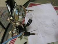
Uriah
I just photoshopped it and then the wife said to get to the couch and I said in a minute and this was the hurried result, but I think it can be followed.
Uriah
post1816 is brilliant.
It can be read by those who cannot read a schematic.
It can be read by those who can read a schematic.
It imparts more information than a conventional schematic.
It can be read by those who cannot read a schematic.
It can be read by those who can read a schematic.
It imparts more information than a conventional schematic.
For those folks that may be slower to solder the LDR leads, it's definitely recommended to use a heatsink clamp (simple spring clip type)- the LDRs MUST be treated with caution.
Well thank you for the warning!!
I am still awaiting boards from Paul but am glad to know AHEAD of time to heed your warning!
I am still awaiting boards from Paul but am glad to know AHEAD of time to heed your warning!
You're welcome - It's an extraordinary little device, regardless of which circuit you use and it's well worth taking some extra trouble with the buffers, if required.
Again, it's a timely thank you to George for this design and support.
Again, it's a timely thank you to George for this design and support.
georgehifi said:For those of you who emailed for a look of the internals, here it is, the potted off white block in the centre of the main board houses the 4 x led/ldr packages, the other board is the second regulation 5vdc board, and not in the pic is a regulated 12vdc plug pack.
Cheers George
Hmm, that looks neat. I've got a question.
I'm sure the case you've selected is sealed shut and doesn't leak in any external light?
Merlin, will sneak in the answer just to show that I was paying attention to georges beexwaxs thingie - the potting/sealing goo to keep the temp the same AND to block nout any stray light (the LDRS DO leak a bit) AND to absorb any viabration effects AND to keep the design confidential, etc.
It's not often that people will not only release the details of their work but will support this with further information - more often as a commercial undertaking, but also sometimes for nothing, apart from the occassional thank you.
One thing that perhaps could do with a reminder - the buffers behind (and before) the Lightspeed do require extremely good supplies to them, regardless of what particular version - these simple ccts are VERY dependent on what the supply rails are doing (or not!)
James,
My friend is sending me some tubes to try. I want to build the buffer George mentioned that uses tubes. Do you have a certain power supply that you suggest? I was just going to use a solid state rectifier, snub it, give it some power caps and call it good. For a solid state buffer I will just probably use my B1 if I ever need it.
Anyone reading this thinking "OH NO I need a what? A Buffer?" dont sweat it. You dont need a buffer in most cases. The buffer is for a mismatch of output and input impedance between your source (CDP) and your amp. For instance with my MyRefC solid state amp there is no need for a buffer of any kind and the Lightspeed makes a huge difference in sound quality from the Alps 10k pot I had inbetween the CDP and Amp before. So try the Lightspeed first and then... if things arent going well you may need a buffer, but in most cases with a CDP and a solid state amp you will NOT need a buffer.
I want to try the tube buffer to see if it gives me that tubey sound 🙂
Uriah
Hi Uriah,
I've been meaning to ask the price of the matched LDR pairs - I missed it on the thread, and my pairs are nowhere as well matched as yours.
Now the valve power supply - what I did for the Aikido buffer O/P was just a simple Wheatfield supply as per the ECC99 SRPP headamp (for the K100 phones) - the supply is okay, but it didn't match well, and it never came good for me, unfortunately.
[then I borrowed one of those China boxes - not so good at all!]
So the valve buffer has been posponed to the auxiliary buffer O/P for the developing DAC and it'll be either that one that George recommends or perhaps the Alex Cavalli OCL design (Heretical design) that has a nice supply that will suit both.
I must admit that not only would I occassionally like some of that valve colour, but l'd also like to reach out and adjust the absent tone controls for much of the music! [that's also on the project long, long list!]
I reckon a good buffer will solve a lot of mismatch problems and reduce the "bad" effects on the sound due to "incorrect" cable matching but, as George says, the best buffer is none, unless absolutely necessary - a really contentious subject, particularly in Pro Audio!
Hope this "shamble ramble" is of use to you.
Originally posted by udailey
I was just going to use a solid state rectifier, snub it, give it some power caps and call it good.
no good.
You need at least a CRC (better yet CLC) "pi" filter or (better) two of them in a row. You may effectively reduce rectification noise (at the expense of some extra voltage drop) by adding some R before the 1st cap. That is, use something like RCRCRC or RCLCLC or a "hybrid" RCLCRC (or RCRCLC).
E.g. for a typical stereo setup use something like:
Code:
                       +-R-C--> (left)
<diode bridge>-R-C-L-C-+
                       +-R-C--> (right)
The last 'C' (on each branch) is the one through which (most of) the audio current loop close. It must be sized to have negligible reactance at 20Hz. The others are smoothing out the rectified AC and need be sized (togheter with series 'R's) to effectively filtering out the 100/120 Hz ripple.
If you use 'L's (inductors), beware of resonances. They must be kept well below the audio band.
As for the diodes, consider silicon carbide Schottky type. They are much quieter than junction types.
udailey said:Is this for the tube buffer or does it not matter?
Uriah
it's good for any application involving more or less constant currents (that is, Class A). Most simple line buffers and pre-amplifiers (either tube, solid state or hybrid) fits.
Of course, if you're after op-amps or other complex SS designs using loop NFB then you'd likely rather choose a PSU design using active voltage regulation instead.
gabanyayaya said:Hi guys,
Got a question here regarding mounting the LDR.....
Which one the best way to attach the LDR....
1 - Is it solder the LDR input lead section directly to input of the RCA and use a shielded wire between the input at the amp pcb and output of the LDR.....or
I took this approach and have been very happy with the performance. I left the LDRs about 1/2 inch up from the board leaving room to attach signal input wires that were hard wired to a DAC. I used CAT5 to wire the LDR attenuator back to a control PCB that had the power supply, pots etc. The LDRs are glued together with silicon seal and encased in shrink wrap. That way there is no external light pollution, and they are heat insulated. I get great performance with no drift.
Attachments
gabanyayaya said:
1 - Is it solder the LDR input lead section directly to input of the RCA and use a shielded wire between the input at the amp pcb and output of the LDR.....or
2 - Solder the LDR output lead section to the amp pcb and run a shielded wire between input of the RCA and input of the LDR.....
I suggest that the LDR is as close to the amp input as is possible because the output from the LDR is high impedance and low level - so more prone to pick up, interference etc.
The input to the LDR is higher level and driven from a low impedance - so less prone to interference
mike
mikelm said:
I suggest that the LDR is as close to the amp input as is possible because the output from the LDR is high impedance and low level - so more prone to pick up, interference etc.
The input to the LDR is higher level and driven from a low impedance - so less prone to interference
mike
If this is a problem, bypass the hot side of the LDR with 100p or 200p
mmmm ?? . . . I thought I was suggesting a solution rather that reporting a problem . . . 
with the LDR's close to the amps I have not experienced any problems and thought the sound was a little better 🙂
with the LDR's close to the amps I have not experienced any problems and thought the sound was a little better 🙂
mikelm said:
I suggest that the LDR is as close to the amp input as is possible because the output from the LDR is high impedance and low level - so more prone to pick up, interference etc.
The input to the LDR is higher level and driven from a low impedance - so less prone to interference
mike
But won't this difficult to do since there's 2 leads together....???
No. They are the output and just twist them together into one lead and solder that one lead to the input of your amp then solder the Ground lead to the signal ground of you amp.
Uriah
Uriah
George,
Have you seen the Melos Gold "Photentiomenter' preamp for sale at Aussie eBay?
http://cgi.ebay.com.au/MELOS-SHA-GO...yZ109837QQssPageNameZWDVWQQrdZ1QQcmdZViewItem
Have you seen the Melos Gold "Photentiomenter' preamp for sale at Aussie eBay?
http://cgi.ebay.com.au/MELOS-SHA-GO...yZ109837QQssPageNameZWDVWQQrdZ1QQcmdZViewItem
- Home
- Source & Line
- Analog Line Level
- Lightspeed Attenuator a new passive preamp