It sounded okay, till he dropped it and broke it off near the throat. After that, despite some gorilla-glue fueled repair attempts, it was never quite the same again. 🙂
Seriously, it did work, though I recall it still had a bit of a honk and some sound leaked through the foam board.
Finally, we did (temporarily) attach some NXT exciters to the contraption to extend its response downwards . The approach did work (though we didn't mess with crossovers etc to optimize the sound) but the horn might have been fractured by that time. I don't recall.
Original thread here : http://www.diyaudio.com/forums/multi-way/153831-styrofoam-smith-horn.html .I've attached the design doc and theory to this post
Thanks for the info, Zobsky. I may have to make this in paper-faced foam core sheets. I have some CD's coming my way soon... Although the pink foam looks like a great material as the thickness is automatically provided. Curved FC can be shaped into those airfoil like dividers easily enough.
xrk971 -- what does an impedance plot of your subs look like at low power vs moderate/high power? (Provided SWMBO...)
That'll probably tell us a lot about the panel flex/resonances from the construction method.
And, yes, skinning these with just about anything (good cardboard probably isn't too bad), but whatever you do, make sure there's a good bond between the two. The foam itself can act as the lossy medium and you're trying to get maximum coupling between the skins to up the panel stiffness. 1" of foam makes for a big I-beam. 🙂
Might have to get some inexpensive 5-6" drivers and see if I can make a mini-sub FLH to go underneath my bed (don't have a "listening room")
From the limited experience of one and only time I tried it,
I can't recommend naked styrofoam wallboard for horns.
Muffled treble leaked through in every direction and ignored
the intended paths.
If you can glaze or wallpaper the interior with something a
little harder than the naked foam structure, might be OK.
Pink for a reason, or is it???
I can't recommend naked styrofoam wallboard for horns.
Muffled treble leaked through in every direction and ignored
the intended paths.
If you can glaze or wallpaper the interior with something a
little harder than the naked foam structure, might be OK.
Pink for a reason, or is it???
Last edited:
Ohyeah, and lets talk glue for a second...
I used expanding polyurethane glue (gorilla) cause it was
chemically compatible with the foam and filled seam gaps.
On the other hand, this stuff was a mess. Smelly, irritaing
if you get any on hands. Impossible to clean the exceess
that ooozes from joints. And the expansion tends to float
the positioned parts from where you had them carefully
aligned and thought they were going to stay. Definately
requires some pins (I havn't actually tried pins) or clamp,
or something. It won't stay put due to gravity and friction
I can tell you that. Way harder than the foam, you ain't
getting any off without tearing the foam.
If I do this again, I'd be looking for a non-expanding caulk
sort of glue that cooperates with forming a clean bead...
Last edited:
Ohyeah, and lets talk glue for a second...
I used expanding polyurethane glue (gorilla) cause it was
chemically compatible with the foam and filled seam gaps.
On the other hand, this stuff was a mess. Smelly, irritaing
if you get any on hands. Impossible to clean the exceess
that ooozes from joints. And the expansion tends to float
the positioned parts from where you had them carefully
aligned and thought they were going to stay. Definately
requires some pins (I havn't actually tried pins) or clamp,
or something. It won't stay put due to gravity and friction
I can tell you that. Way harder than the foam, you ain't
getting any off without tearing the foam.
If I do this again, I'd be looking for a non-expanding caulk
sort of glue that cooperates with forming a clean bead...
Aquarium grade silicone, or even liquid nail would work well.
Possibly even 5 minute epoxy, which can be found at dollar stores, could be fine.
Yay someone finally built my design
I haven't been on DIYaudio in almost a year, but for that whole year I was dreaming about theDual opposed slot loaded sub. I assumed that thread and the design had fallen into obscurity. Not only is it alive but it has a better name! 😀
Xrk, you are the MAN! Thank you, I'm so happy. I have so many questions about what you have discovered in your work, but I suppose I better read the thread first. 😀
This week I finally started my first implementation of a SLBP(cool acronym too!). I'm doing it for a car sub for a friend of mine with two tang band W8-740P. The slot loaded style is ideal as he has a wagon (Audi allroad) with lots of stuff being moved around in the trunk; so having the woofers protected is key. One little twist is that I'm sloping the back panel so it fits right up against the seat. This effectively makes the port triangular in the first two sections. Also the speaker will not fit in the slot, so I'm putting access hatches on the bottom.
Lastly, I figured out how to roughly sim it in winISD pro! Using the 6th order bandpass mode I choose an arbitrary front tuning frequency(200hz seems to work) and through iterative guessing, I try to make the front vent length approach zero. Often times I have to re-enter the front tuning frequency in the box tab when the program freaks out. This is very rough because the front chamber and last section of the rear port are one in the same so I don't know if I count the front chamber in the rear port length or not. Eventually, once we collect enough experimental data for an accurate model, I think a spreadsheet or online calculator is in order.
But for now I've got some thread reading to catch up on.
Keep up the good work Xrk!
-Matt Long
Thanks for the kind words! You will like this thread:
http://www.diyaudio.com/forums/subwoofers/264737-pp-slot-loaded-sub-alpine-swr-12d2.html
Just what you are talking about - mounting in the trunk with slot vent through back seat. 🙂
Hi X,
"... kind of a funny skinny shape..."
Yes, that shape might work nicely for a bench or a stand. I'll attach another sketch that has two versions w/ a lower height, and greater depth. Just thought concepts. Maybe somebody need something lower but still with the PPSL concept. I have not tried to put this into AkAbak though.
Regards,
Tb46
Do you have a detail drawing for this plan. I want to build one for my computer with a build in plate amp. The drivers used in this plan is $30ea, which is not bad. Will a 200 watt plate amp do?
Thanks
Sold on the push pull slot loaded concept then? 🙂
This sub with a pair of the 8in MCM 55-2421's will really rock your computer. Are you sure you need that much sub under your desk? 😀
How is the Alpine box coming along - anxiously waiting for first sound reports.
This sub with a pair of the 8in MCM 55-2421's will really rock your computer. Are you sure you need that much sub under your desk? 😀
How is the Alpine box coming along - anxiously waiting for first sound reports.
Sold on the push pull slot loaded concept then? 🙂
This sub with a pair of the 8in MCM 55-2421's will really rock your computer. Are you sure you need that much sub under your desk? 😀
How is the Alpine box coming along - anxiously waiting for first sound reports.
Not too much bass for me. lol. I love the push pull slot loaded.
I will install the Alpine drivers this weekend and fired it up.
What o you think of this speaker to use in this design.
They are $10ea
Last edited:
Lawbiding,
That is a neat driver - if you can believe the TS specs - I can't believe the Qts is 0.37 for how small the magnet is and how low the price is. If someone has measured the TS then we can design a speaker cabinet for it. At $10 it is a good deal to get for some cheap sealed or even as a bass for a low cost Trynergy.
Tb46,
What do you think of the TS params? Too good to be true?
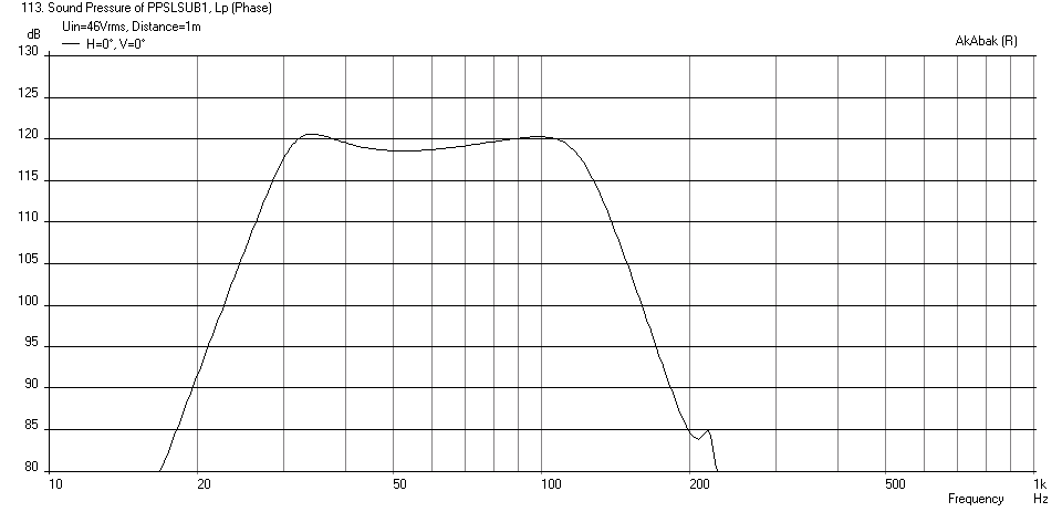
I tweaked the design some more to flatten it and to set the bass extension at 30 Hz (-3dB) while trying to minimize the volume to keep it small. To do this, I am using a corner room placement typical of how a sub like this will be used (in my experience) to give the added bass gain that enables a smaller box. The design ended up at 18.5 liters per chamber with 0.75 in deep x 10 in tall x 24 in long slot vents leading to a central push-pull slot-loaded vent that is 4.75 in wide (to fit drivers in push-pull) x 10 in tall x 10 in deep. A 27 Hz -24dB/oct HPF is used to prevent over-excursion and it has wide bandwidth up to nearly 200 Hz if you wanted to use it that far. I have opted for a 120 Hz -48dB/oct LPF that should let this integrate well with many systems (or set it lower if you want). Here is the predicted response at max drive voltage of 46 volts.
I am fascinated by your continual inventiveness xrk971.
I have four Dayton DCS205-4 and thought they would pretty well substitute for the MCM 55-2421?
Is there any difference between the facing mounting on the 5" speakers and the inline mounting of the 8" speakers?
I assume they move in phase?
By the way I bought 60 TC9FD-18-08's. 50 for Line Arrays and 10 to experiment with your foamcore designs. i like your MLTL's as you can hang them on the wall.
Anyway thanks for all the ideas.You have taken me into new fields of thought.
Paul
Coit,
Thanks for the kind words! If you are interested in these PP SL Bandpass sub designs, check out this thread where members Tb46 and lawbiding have teamed with me to build plywood variants of this sub. The latest build from lawbiding uses the MCM 55-2421 but in an asymmetric chamber design by Tb46. The thread is here:
http://www.diyaudio.com/forums/subwoofers/266582-alpine-swr-12-10-mesurement-bandwith-response-curve.html
Both of these guys work very fast and I can't keep up with them. When the builder (constructor) works faster than the designer (modeler), you know that has to be fast. 🙂
I just wish I could hear these creations, alas all I have are measurement plots and prediction curves.
If you want to use the Dayton DCS205-4, which look like great drivers suitable for PPSL Bandpass design, I can try to run a quick sim for you to optimize the channels and vent dimensions. It will probably work but TS params are slightly different than MCM 55-2421.
That is really cool that you have 60 little Vifa TC9FD's. 😀 Are you going to build something similar to Wesayso's Twin Towers? The IDS-25 design is a great one and your really can't go wrong. With DSP being so inexpensive nowadays, you don't even have to do the analog EQ. Although, Bob Richards and I both worked on what is probably a pretty good analog EQ circuit for it in the "Cloning IDS-25" thread.
Good luck and have fun! Those MLTL's are easy to make in FC, please post pics in FC thread if you make them.
Thanks,
X
The DCS220-4 is drop in replacement for MCM 55-2421
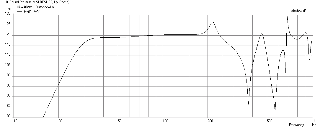
Here is a sim of the box that Tb46 drew up. It appears that the design can use the Dayton DCS220-4 as a drop in replacement. You just have to back off on the drive voltage a tad. But the predicted performance is very nice. Subs don't get much flatter with as wide of a bandwidth as this. 119 dB SPL at 1m (with corner placement) and -3dB is at 29Hz. To be clear, since Tb46 is so prolific with his drawings, this sim is based on this design:
http://www.diyaudio.com/forums/attachments/subwoofers/428991d1405626797-light-air-slot-loaded-band-pass-sub-xrk971_55-2421_ppsl.pdf
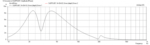
Corner loaded placement SPL at xmax of 8.8mm and 40 volts drive (with -24dB/oct BW high pass at 25Hz):
Cone excursion at 40 volts:

Here is a sim of the box that Tb46 drew up. It appears that the design can use the Dayton DCS220-4 as a drop in replacement. You just have to back off on the drive voltage a tad. But the predicted performance is very nice. Subs don't get much flatter with as wide of a bandwidth as this. 119 dB SPL at 1m (with corner placement) and -3dB is at 29Hz. To be clear, since Tb46 is so prolific with his drawings, this sim is based on this design:
http://www.diyaudio.com/forums/attachments/subwoofers/428991d1405626797-light-air-slot-loaded-band-pass-sub-xrk971_55-2421_ppsl.pdf
Corner loaded placement SPL at xmax of 8.8mm and 40 volts drive (with -24dB/oct BW high pass at 25Hz):
Cone excursion at 40 volts:
Attachments

Last edited:
Hi X,
I missed your question in Post #92 on the buyout 8" lawbiding links to in Post #91. The price looks just great $10.--ea. $9.--ea.@Qty.8. The T/S parameters seem to add up in Hornresp, and don't look completely out off this world.
Might be fun to play around w/ in isobaric arrangements?
Sadly, I don't have any shelf space left. 🙂
Regards,
Hi X,
I missed your question in Post #92 on the buyout 8" lawbiding links to in Post #91. The price looks just great $10.--ea. $9.--ea.@Qty.8. The T/S parameters seem to add up in Hornresp, and don't look completely out off this world.
Might be fun to play around w/ in isobaric arrangements?
Sadly, I don't have any shelf space left. 🙂
Regards,
I just don't believe you can have a driver with such a small ferrite magnet and have Qts that low. Does anyone have data on these guys?!
Thankyou for the sim; man that's flat.I'll make two and if necessary use them with the line array.
I stumbled across the Murphy Corner Line Array and have to build it (not to Wesayso's standards I'm affraid ).
The MLTL's I cut today out of 3mm MDF ( 6lbs each ),as Foamcore is hard to get and expensive here.
Thanks again for your replies and help.
Paul
I stumbled across the Murphy Corner Line Array and have to build it (not to Wesayso's standards I'm affraid ).
The MLTL's I cut today out of 3mm MDF ( 6lbs each ),as Foamcore is hard to get and expensive here.
Thanks again for your replies and help.
Paul
Last edited:
Make 1 first to be sure it works before making two 🙂 although this design has been proven to work with similar drivers so I am quite sure the sim is good.
- Home
- Loudspeakers
- Subwoofers
- Light as Air Slot Loaded Band Pass Sub