Hi Y'all,
I'll attach my notes on the MCM 55-2421 build, it's not a drawing, just a sketch for note keeping:
Regards,
Tb46,
Thanks!!! that looks very nice - you say it is not a "drawing" but sure looks to scale to me, as in it was made in Acad...
It's kind of a funny skinny shape but that can work well as it has a tiny footprint if stood on end and shoved into a corner like a broom.
Cheers,
X
Hi X,
"... kind of a funny skinny shape..."
Yes, that shape might work nicely for a bench or a stand. I'll attach another sketch that has two versions w/ a lower height, and greater depth. Just thought concepts. Maybe somebody need something lower but still with the PPSL concept. I have not tried to put this into AkAbak though.
Regards,
Attachments
Akabak script
Tb46,
Thanks for the drawings and for looking at a subby variant. Here is the script, knock yourself out in Akabak sim-land 🙂
Hi nbriles2000,
"...not enough room for the driver..."
The drivers are supposed to be mounted from the slot side, not from inside the chambers. If you build only one side you are missing the PPSL effect of distortion reduction.
Regards,
Tb46,
Thanks for the drawings and for looking at a subby variant. Here is the script, knock yourself out in Akabak sim-land 🙂
Code:
| Push Pull Slot Loaded Subwoofer
| PPSLSUB1
| July 16, 2014
| by xrk971
| with dual MCM 55-2421 8 in drivers

Def_Const
{
Q=0.707;

Speaker_pos=5.0*0.0254;  | Height of centerline of exit port above floor
Width=28.0*0.0254;  | Width of cabinet external
Height=11.5*0.0254; | Height of cabinet external, 24 in long chamber ea + slot
Depth=16.5*0.0254;  | Depth of cabinet 14 in deep internal
Dist_wall=5000*0.0254;  | Distance from wall

| ****

Backchamber_vol=37.0*0.001;  | 37 L gives 12.5in L x 10in H x 9in deep

Slot_width=4.75*0.0254;  | needs to wide enough to fit driver in push-pull
Slot_height=10.0*0.025;  | height accounts for bracing reduction in CSA
Slot_length=10.0*0.0254; | lenght of two ducts that form slot deep enough to house 18 in driver

| *** dual rear resistance vents

Vent_width=0.75*0.0254;
Vent_height=10.0*0.0254;
Vent_length=24.0*0.0254;

}

System 'PPSLSUB1'

Def_Driver  'MCM55-2421' | 8 in, Qts 0.22, 8 mm xmax, 87dB, 8.25 in dia, 7.125 cutout, Jan 17 2014
  SD=208.7cm2   |Piston
  fs=25.7Hz
  Mms=59.8g
  Qms=14.00
  Qes=0.22
  Re=3.4ohm
  Le=2.47mH
  Vas=30.4L

|OFF
Filter    'High Pass'  | 4th order Butterworth -24dB/oct
    fo=27Hz  vo=1.0
    {b4=1;
     a4=1;  a3=2.613126;  a2=3.414214;  a1=2.613126;  a0=1;  }
|OFF
Filter 'LowPass' |Lowpass filter - 48dB Butterworth (change 'fo=***' and refresh for changes)
fo=120Hz vo=1
{b0=1;
a8=1; a7=5.125831; a6=13.137071; a5=21.846151; a4=25.688356; a3=21.846151; a2=13.137071; a1=5.125831; a0=1; }

|OFF
| Speaker placed in corner with driver at Driver_pos above floor in corner
Def_Reflector  BottomCorner
Bottom={Speaker_pos}  Left=17in Right=17in
HAngle=0  VAngle=0

OFF
| Speaker with driver at Driver_pos above floor Dist_wall away from wall
Def_Reflector  HorizEdge
Bottom={Speaker_pos}  Top={Depth + Dist_wall}
HAngle=0  VAngle=0

Enclosure  'Back chamber 1'  Node=10
Vb={Backchamber_vol/2}  Qb/fo={Q}  Lb=10in

Enclosure  'Back chamber 2'  Node=20
Vb={Backchamber_vol/2}  Qb/fo={Q}  Lb=10in

Driver Def='MCM55-2421' 'Driver 1'
Node=2=1=30=10

Driver Def='MCM55-2421' 'Driver 2'  | driver 2 is reverse mounted with phase reversed
Node=0=2=30=20

Duct    'D3'  Node=31=30  | rear half of output slot
    WD={Slot_width}  HD={Slot_height}  Len={Slot_length/2}

Duct    'D4 Slot'  Node=30=32   | front half of output slot
    WD={Slot_width}  HD={Slot_height}  Len={Slot_length/2}

Duct    'D1 Vent'  Node=10=31   | resistance vent 1 leading to slot
    WD={Vent_width}  HD={Vent_height}  Len={Vent_length}

Duct    'D2 Vent'  Node=20=31   | resistance vent 2 leading to slot
    WD={Vent_width}  HD={Vent_height}  Len={Vent_length}

Radiator 'Vent_rad'
Def='D4 Slot'
Node=32
x=0  y=0  z=0
HAngle=0  VAngle=0
WEdge={Width/2}  Hedge={Height/2}
Reflection
Last edited:
Nbriles2000,
Are you going to build the MCM55-2421 half-a-PPSL sub? You have the plans and the sims now... Look forward to hearing how those 8 in budget MCM's sound.
Are you going to build the MCM55-2421 half-a-PPSL sub? You have the plans and the sims now... Look forward to hearing how those 8 in budget MCM's sound.
I haven't decided if I want to try that PPSL or the 10L with a passive radiator!
I really think I want to try the smaller one, but I'll probably buy the driver and mess around with different stuff when I get paid
I really think I want to try the smaller one, but I'll probably buy the driver and mess around with different stuff when I get paid
Klbird,
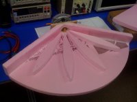
Hey thanks! I thought about the thin wood facing for the driver mounting too and it would have been nice but then would have been counter the "no power tools and no sawdust" goal that I have set for myself. I ended up using pieces of triple wall cardboard glued to the back side of the foam as "nuts" for the wood screws to bite into and hold the drivers. So far not one piece of wood was touched in this project.
X
Hey that is my philosophy on my projects. My Japanese pull saw gets a lot of workout.
Design for Sundown Audio 8V2 driver
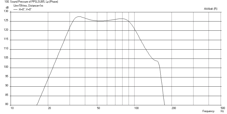
Chrapladm requested a design for a sub that could use the 8inch SA 8V2 driver (which has 16 mm xmax and 500 watts RMS power handling - SA Series).
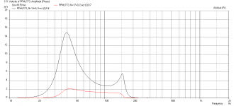
It turns out that with very minor tweaking of the geometry used in the MCM55-2421 that Tb46 came up with above allows this driver to work pretty well as a sub that has 31Hz (-3dB) and capable of about 125dB (at 1kW to the pair power limited not xmax limited) when corner loaded.
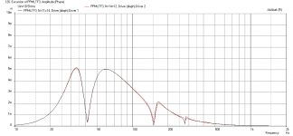
The final design ended up at exactly 1 cu ft volume per driver rear chamber, a 7.5 in wide x 10 in tall x 14 in long central P-P slot vent, and the only tricky part is the very long vent which will require a labyrinth to fold 36 in long 1.0 wide x 10 in tall slot vent per side into the box. Note that the slot is a rather wide 7.5 in to fit the 6-5/8 in deep driver in a push-pull config.
Here is the predicted SPL vs freq at max power of 70 volts RMS:
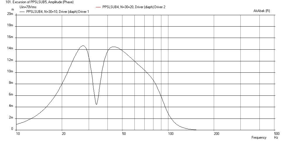
Here is the corresponding cone displacement with a 29Hz -24dB HPF and a 90Hz -48dB/oct LPF:
Chrapladm requested a design for a sub that could use the 8inch SA 8V2 driver (which has 16 mm xmax and 500 watts RMS power handling - SA Series).
It turns out that with very minor tweaking of the geometry used in the MCM55-2421 that Tb46 came up with above allows this driver to work pretty well as a sub that has 31Hz (-3dB) and capable of about 125dB (at 1kW to the pair power limited not xmax limited) when corner loaded.
The final design ended up at exactly 1 cu ft volume per driver rear chamber, a 7.5 in wide x 10 in tall x 14 in long central P-P slot vent, and the only tricky part is the very long vent which will require a labyrinth to fold 36 in long 1.0 wide x 10 in tall slot vent per side into the box. Note that the slot is a rather wide 7.5 in to fit the 6-5/8 in deep driver in a push-pull config.
Here is the predicted SPL vs freq at max power of 70 volts RMS:
Here is the corresponding cone displacement with a 29Hz -24dB HPF and a 90Hz -48dB/oct LPF:
Attachments
I will have to see if i could even build that in such a narrow width cabinet. I could do a PP with the drivers horizontal but if I went with the traditional vertical alignment I would end up being almost 14" wide. If I go that wide I might as well use a bigger driver. I am trying to stick with a roughly 10" wide baffle.
Labyrinth would fine. I would just have to squeeze two long ports in my cabinet is all. BUT in saying all that I could place this PP on the side of the cabinet and not the baffle. Its an option I will have to consider.
Labyrinth would fine. I would just have to squeeze two long ports in my cabinet is all. BUT in saying all that I could place this PP on the side of the cabinet and not the baffle. Its an option I will have to consider.
The baffle is 10 in wide (internal), it will be like 18 in deep though to make room for the labyrinth channels though. It will stand vertically to take little floor space in the corner.
I will have room vertically so I can probably fit this...... possibly. I have a lower case "b, shape space to work with. The whole cabinet will be about 52" tall. SO I will try and keep this as shallow as possible. So around 17" max is ok but 15 would be better.
Push-Pull ML-TransFlex (PP MLTF)
From some work I did on modeling a PP MLTF in this thread: http://www.diyaudio.com/forums/subwoofers/259509-new-sub-design-constricted-transflex-simple-build-series-tuned-6th-order-17.html#post4029749 I realized that it might be advantageous to convert the SLBP sub into this alignment with a few steps:
1. extend the length of the chamber to support 1/4-wave action
2. combine the two chambers into one in order to make more compact by allowing the drivers to be mounted push-pull on the same baffle but one flipped.
3. Convert the long thin vent to a larger cross section to serve as a mass-loading duct for the TL.
4. Have the ML duct exit into a common outer driver chamber/mouth where the sound radiates and this allows the 6th order bandpass action to happen.
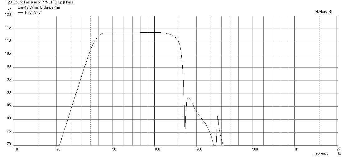
So I came up with a much more compact design for the dual W5-876SE that is now 16in (W) x 16in (H) x 12in (D) - assuming 0.5in thick panels. Here is the predicted frequency response at xmax (18.5 volts) when corner loaded. A 38Hz 24dB HPF and 150Hz 48dB LPF were applied:
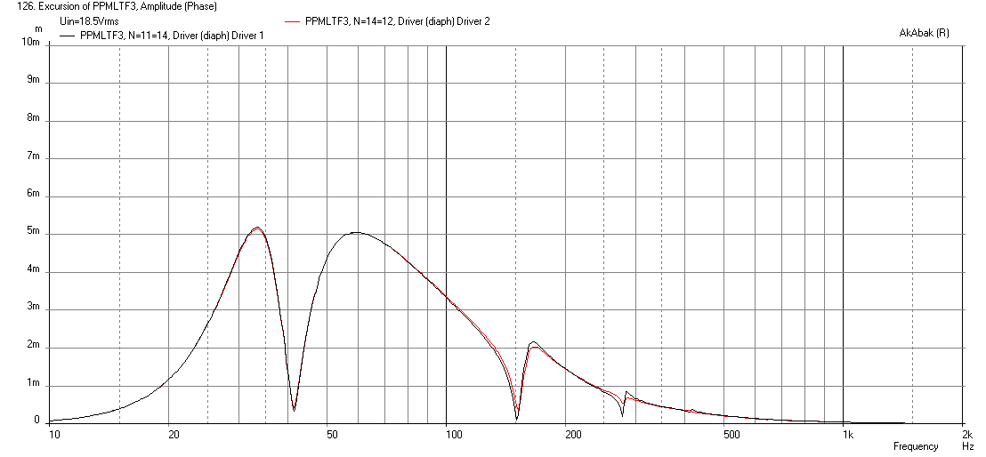
Here is the cone displacement at xmax:
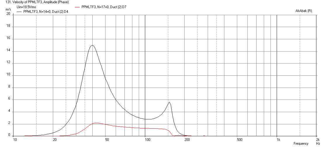
Here are the vent and mouth exit velocities at xmax (all good):
Although it is corner loaded, the sensitivity obtained with a couple of 5 inch drivers is remarkable, and the response is very flat from 40Hz to 150Hz.
From some work I did on modeling a PP MLTF in this thread: http://www.diyaudio.com/forums/subwoofers/259509-new-sub-design-constricted-transflex-simple-build-series-tuned-6th-order-17.html#post4029749 I realized that it might be advantageous to convert the SLBP sub into this alignment with a few steps:
1. extend the length of the chamber to support 1/4-wave action
2. combine the two chambers into one in order to make more compact by allowing the drivers to be mounted push-pull on the same baffle but one flipped.
3. Convert the long thin vent to a larger cross section to serve as a mass-loading duct for the TL.
4. Have the ML duct exit into a common outer driver chamber/mouth where the sound radiates and this allows the 6th order bandpass action to happen.
So I came up with a much more compact design for the dual W5-876SE that is now 16in (W) x 16in (H) x 12in (D) - assuming 0.5in thick panels. Here is the predicted frequency response at xmax (18.5 volts) when corner loaded. A 38Hz 24dB HPF and 150Hz 48dB LPF were applied:
Here is the cone displacement at xmax:
Here are the vent and mouth exit velocities at xmax (all good):
Although it is corner loaded, the sensitivity obtained with a couple of 5 inch drivers is remarkable, and the response is very flat from 40Hz to 150Hz.
Attachments
Too bad akabak doesn't show enclosure shapes like HR.
I actually started with the physical dimensions I desired and had a fold plan ab initio. I translated this into elements in Akabak and then fine tuned the mass loading vent in the simulation.
Great results although this is all over my head. Still have to work out how to design a basic TL or quarter wave design.
When I cut the styrofoam Smith horn, I had a lot of trouble with knives and saws
dragging and tearing as much as cutting. Eventually resorted to a guitar string on
a bamboo bow, heated by a car battery charger...
dragging and tearing as much as cutting. Eventually resorted to a guitar string on
a bamboo bow, heated by a car battery charger...
Attachments
Last edited:
When I cut the styrofoam Smith horn, I had a lot of trouble with knives and saws
dragging and tearing as much as cutting. Eventually resorted to a guitar string on
a bamboo bow, heated by a car battery charger...
Your Smith horn looks fantastic! How does it sound? I had good luck cutting straight lines with a brand new box cutter blade. Get the ones that break off. When it starts to drag and make rough cuts get a new one. Your curves may be difficult to get clean like that with anything other than a hot wire. For the Smoth horn where did you get the dimensions or is this your own design?
Your Smith horn looks fantastic! How does it sound?
It sounded okay, till he dropped it and broke it off near the throat. After that, despite some gorilla-glue fueled repair attempts, it was never quite the same again. 🙂
Seriously, it did work, though I recall it still had a bit of a honk and some sound leaked through the foam board.
Finally, we did (temporarily) attach some NXT exciters to the contraption to extend its response downwards . The approach did work (though we didn't mess with crossovers etc to optimize the sound) but the horn might have been fractured by that time. I don't recall.
Original thread here : http://www.diyaudio.com/forums/multi-way/153831-styrofoam-smith-horn.html .I've attached the design doc and theory to this post
Attachments
Last edited:
- Home
- Loudspeakers
- Subwoofers
- Light as Air Slot Loaded Band Pass Sub