A quick question if I may.
If one chamber contains a driver and the other doesn't,
shouldn't the chamber with driver be bigger by the amount
of the driver volume (in my case 0.62l)?
Or should I build like your original with drivers in both chambers?
thanks
Paul
If one chamber contains a driver and the other doesn't,
shouldn't the chamber with driver be bigger by the amount
of the driver volume (in my case 0.62l)?
Or should I build like your original with drivers in both chambers?
thanks
Paul
A quick question if I may.
If one chamber contains a driver and the other doesn't,
shouldn't the chamber with driver be bigger by the amount
of the driver volume (in my case 0.62l)?
Or should I build like your original with drivers in both chambers?
thanks
Paul
If you are only using 1 driver you don't need other chamber at all.
If you are only using 1 driver you don't need other chamber at all.
I meant in the diagram there is one driver in the left chamber and one driver in the centre vent working push-pull.There is no driver chassis in the right chamber.
In your original design there is a driver in each chamber.
thanks
Paul
PS: Sorry if question seems stupid.
Last edited:
Yes, you should make chamber volumes account for volume of driver frame/magnet/cone displacement. That will be best I just did not do that because I did not know the volume of my driver.
Yes, you should make chamber volumes account for volume of driver frame/magnet/cone displacement. That will be best I just did not do that because I did not know the volume of my driver.
I am sorry to keep harping on this.
In your original design with a speaker in each chamber I would naturally allow for the speaker displacement volumes.
In the design by Tb46 one of the speakers is in the centre vent.
Do I allow for speaker displacement volume increases in both chambers or only in the one on the left that actually contains a speaker?
Is there any advantage to having one driver in the vent?
If you would like,I'll send you a bottle of aspirin.
thanks
Paul
Attachments
I am sorry to keep harping on this.
In your original design with a speaker in each chamber I would naturally allow for the speaker displacement volumes.
In the design by Tb46 one of the speakers is in the centre vent.
Do I allow for speaker displacement volume increases in both chambers or only in the one on the left that actually contains a speaker?
Is there any advantage to having one driver in the vent?
If you would like,I'll send you a bottle of aspirin.
thanks
Paul
If you want to compensate the volume only change the back chamber that doesn't have the magnet in it. Leave the vent duct alone. The reason one is flipped is so that the inherent distortion in the mechanical suspension is cancelled by having one flipped. Hence push pull.
New design for murphmann drivers
I got a request from murphmann to design a slot loaded push pull band pass box with his drivers that have the following specs:
Sd=153cm2 | based on 5.5 in piston dia
Qms=3.1389
Qes=0.432
Mms=34g
fs=48.45Hz
Vas=10.48L
Le=0.286mH
Re=2.023ohm
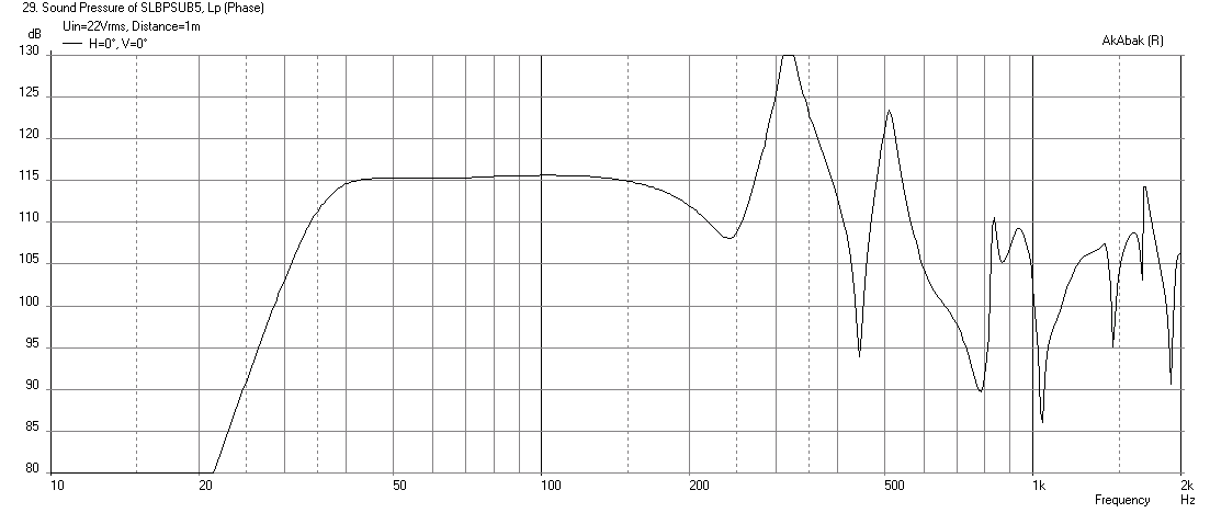
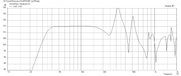
The design I came up with has -3dB point at 36Hz and good sensitivity in corner placement.
Deign is as follows:
Chamber volume for each driver is 12.5 liters
Main output slot with push-pull mounted drivers wired in series:
Slot_width=5.0 in
Slot_height=8.0 in
Slot_length=8.5 in
Dual resistance vents, dimensions for each:
Vent_width=0.5 in
Vent_height=8.0 in
Vent_length=14.0 in
Following sims assume corner placement for optimal loading and bass gain...
Sims also use 33Hz 24dB/oct HPF
Here is the predicted SPL at 2.83v drive:

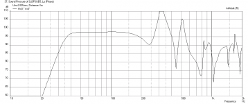
Here is the predicted SPL at assumed xmax of 5mm:

Here is the cone displacement at xmax (22 volts drive):
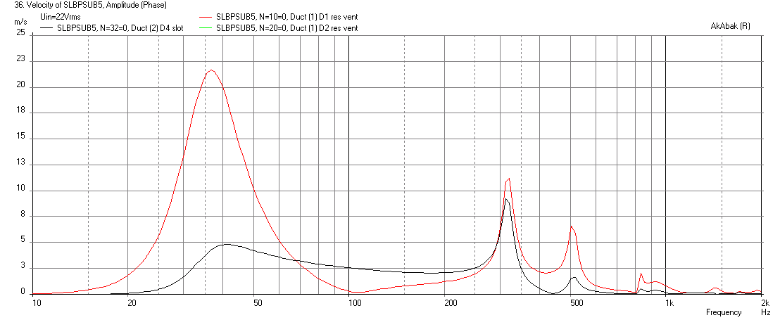
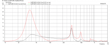
Here are the slot and vent max velocities at xmax:
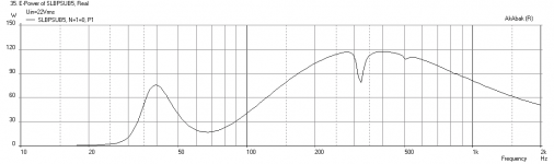
Here is the electrical power needed:

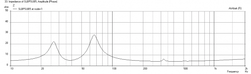
Here is the impedance that the amp will see:

I got a request from murphmann to design a slot loaded push pull band pass box with his drivers that have the following specs:
Sd=153cm2 | based on 5.5 in piston dia
Qms=3.1389
Qes=0.432
Mms=34g
fs=48.45Hz
Vas=10.48L
Le=0.286mH
Re=2.023ohm
The design I came up with has -3dB point at 36Hz and good sensitivity in corner placement.
Deign is as follows:
Chamber volume for each driver is 12.5 liters
Main output slot with push-pull mounted drivers wired in series:
Slot_width=5.0 in
Slot_height=8.0 in
Slot_length=8.5 in
Dual resistance vents, dimensions for each:
Vent_width=0.5 in
Vent_height=8.0 in
Vent_length=14.0 in
Following sims assume corner placement for optimal loading and bass gain...
Sims also use 33Hz 24dB/oct HPF
Here is the predicted SPL at 2.83v drive:
Here is the predicted SPL at assumed xmax of 5mm:
Here is the cone displacement at xmax (22 volts drive):
Here are the slot and vent max velocities at xmax:
Here is the electrical power needed:
Here is the impedance that the amp will see:
Attachments
-
 SLBPSUB5-murphmann-SPL-2.83v.png33.6 KB · Views: 1,057
 -
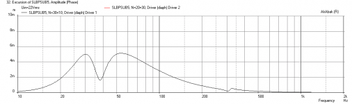 SLBPSUB5-murphmann-displ-xmax.png22.6 KB · Views: 1,058
 -
 SLBPSUB5-murphmann-max-SPL.png33.5 KB · Views: 1,064
 -
 SLBPSUB5-murphmann-max-velocity.png34.2 KB · Views: 1,052
 -
 SLBPSUB5-murphmann-Elect-Power.png12.8 KB · Views: 1,063
 -
 SLBPSUB5-murphmann-Impedance.png21.6 KB · Views: 1,044
I haven't popped by here in a while, opened the list, saw this thread, have to comment.
1) another extremely cool idea you have going here xrk971, you are prone to those 😉
2) I am knee deep in some foam build intended as durability tests for pro use, obviously I'm not leaving them just foam, I'm skinning them inside & out with 18oz fiberglass. But I just had to know how well fiberglassed foam would survive in a pro environment...it's great out of the gates, but will it turn into 2 concentric fiberglass bags with foam dust in between in 6 months? Dunno yet, but I will in 6 months 😀
I'll start a thread about these in a few weeks, too busy building the test victims now...but an 8" coax monitor pair are already built & they sound bloody great, and I've started on a set of foam&glass Jbell SS18
Trackzilla,
Thanks for the kind words. 🙂
Looking forward to seeing your surfboard speakers. You may be right about the turn into two bags filled with dust if you abuse them with impacts from loading and unloading in pro environment. Thin wood stringers are used to resist compressive forces. The other thing you can try is honeycomb cardboard panels used for cargo pallets. Glass that and you have a stiff shell and compression force resistance. Another one is Gatorboard - although that is pricey. Looking forward to the light as air 18 in SS18 tapped horn!
@trackzilla
I did use 1/2 foam along with west system epoxy and 16 oz fiberglass. I did 2 layers of fiberglass on the outside of 1 top I built (12" horn loaded top), with a 1/2 plywood baffle for the driver.
It held up nicely for a while until I dropped it 5 feet off a truck... 😛
I did use 1/2 foam along with west system epoxy and 16 oz fiberglass. I did 2 layers of fiberglass on the outside of 1 top I built (12" horn loaded top), with a 1/2 plywood baffle for the driver.
It held up nicely for a while until I dropped it 5 feet off a truck... 😛
Sine143, Did you only glass them on the outside, or did you skin them inside and out? The strength and rigidity go up exponentially if both surfaces are done.
I don't think a plywood box would survive a 5ft drop. Maybe an all aluminum or steel one would but it would be dented and bent unless very thick.
yeah truth be told i'm afraid the woofer magnets would shear right off if the box hadnt failed given the drop.
Thankyou for the sim; man that's flat.I'll make two and if necessary use them with the line array.
I stumbled across the Murphy Corner Line Array and have to build it (not to Wesayso's standards I'm affraid ).
The MLTL's I cut today out of 3mm MDF ( 6lbs each ),as Foamcore is hard to get and expensive here.
Thanks again for your replies and help.
Paul
Any progress on the dual DCS205-4 subs?
Almost ready to start. Had to make two more MLTL's for niece and friend,both with crappy computer speakers.Music sounds much better with a bit of distance. 3116's are crystal clear.
Styrofoam construction note.
Although in some respects styrofoam (closed-cell extruded polystyrene foam) has acoustic properties the opposite of what you'd ordinarily want, it sure is put to good use in this impressive (and validated!!!) design by xrk971.
It can be easy to work with. Esp out of doors to avoid gases and little loose piece flying around.
There's a special glue usually found in large caulk tubes, strong, light blue colour, fills space, dries in a few hours, low odor, easy to work with, the caulk guns are cheap, and I think it is water soluble.
A hot wire cuts styrofoam easily. But the high road for DIYaudio is to buy a "tile cutter" tip for a pistol-grip transformer-type low-voltage instant-heating soldering iron. Use a metal straight-edge and the cuts will be swell... once you get the hang of it.
Ben
Styrofoam construction note.
Although in some respects styrofoam (closed-cell extruded polystyrene foam) has acoustic properties the opposite of what you'd ordinarily want, it sure is put to good use in this impressive (and validated!!!) design by xrk971.
It can be easy to work with. Esp out of doors to avoid gases and little loose piece flying around.
There's a special glue usually found in large caulk tubes, strong, light blue colour, fills space, dries in a few hours, low odor, easy to work with, the caulk guns are cheap, and I think it is water soluble.
A hot wire cuts styrofoam easily. But the high road for DIYaudio is to buy a "tile cutter" tip for a pistol-grip transformer-type low-voltage instant-heating soldering iron. Use a metal straight-edge and the cuts will be swell... once you get the hang of it.
Ben
Thanks for the note Bentoronto. 🙂
I have personally found a sharp new blade on a utility knife (break of the scored line for a new one) with 5 to 6 gradual stokes, makes PERFECT smooth cuts with no snagging or clumps of foam broken off. I have also found that the inexpensive non-volatile aromatic Liquid Nails (LN) bonds the stuff very well. after applying the LN, I add a few drops of hot melt glue on the corners and middle to tack the board in place. The LNs dries in 24 hrs and fully cures in 48hrs. Add a fillet of LN and smooth to a nice radius with finger at all joints for a very sturdy bond.
The construction is super quick, very clean (no sawdust), needs no tools beyond a razor and a straight edge. 1-in think XPS is quite stiff. I then bond 1/4in thick Sureply on one face and you have an excellent lightweight speaker construction material.
Check out my latest XPS project here: http://www.diyaudio.com/forums/full-range/273524-10f-8424-rs225-8-fast-ref-monitor.html
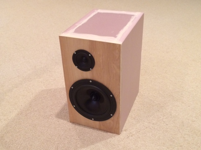
1st Order XO:
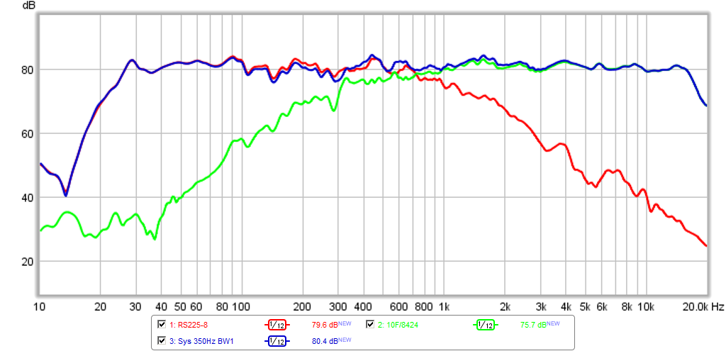
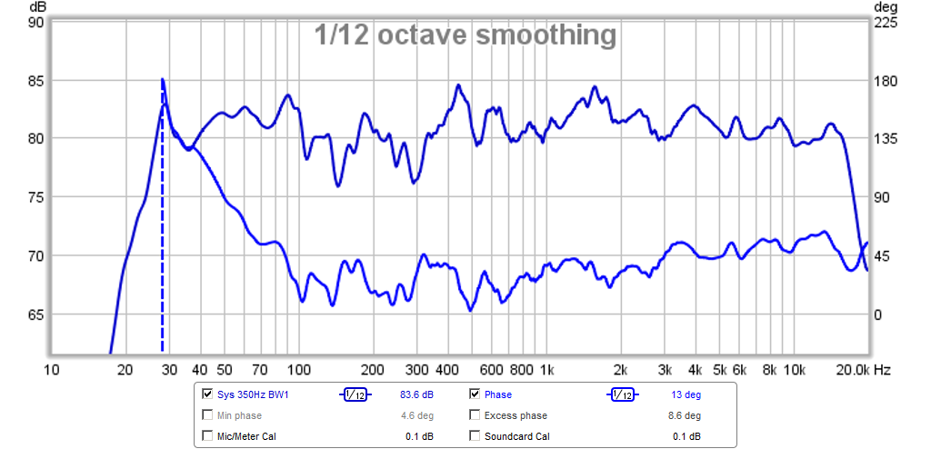
SPL and Absolute Phase:
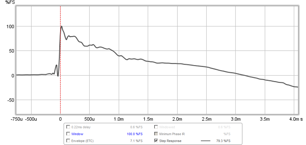
Step Response:
I built this sub with a pair of MCM drivers and have run into a problem. I was very careful in the construction, particularly with sealing all of the edges.
I have a 100hz Parts Express crossover which worked well, and at very quiet volumes, the sub blends nicely into my main drivers. At anything over very quiet volumes, the whole thing buzzes and there appears to be a LOT of driver excursion. Is this something the 25hz HPF would likely fix, or do I simply need to do a tear-down and re-glue?
I have a 100hz Parts Express crossover which worked well, and at very quiet volumes, the sub blends nicely into my main drivers. At anything over very quiet volumes, the whole thing buzzes and there appears to be a LOT of driver excursion. Is this something the 25hz HPF would likely fix, or do I simply need to do a tear-down and re-glue?
Which plan did you go with and did you use bracing for the inside ? Is the buzzing the foam walls moving or the driver cone flapping? It should have good cone motion control. What kind of screws are you using and did you use wood backer plates to give the screws purchase to hold the driver tight?
Some photos would be helpful if you want to debug. My foam box did not buzz - sounds like a loose screw that pulled out.
Some photos would be helpful if you want to debug. My foam box did not buzz - sounds like a loose screw that pulled out.
- Home
- Loudspeakers
- Subwoofers
- Light as Air Slot Loaded Band Pass Sub