Terry,
for someone claiming to be a novice you sure build a nice amplifier.
Looks to me like a flawless piece of work, you have an eye for detail.
Secondly, for the output of your amplifier i'd think from the size of the heatsinks cranking up the bias would be a nice option.
Love the skid plating, i vision your amplifier sitting on the bed of a pickup truck.
Howcome i see 2 amplifier boards and 3 sets of connecting posts?
Terry,
Take a look at:
"Diagram showing wiring of R61 and R63 to the sockets of Q18, Q20, Q28, and Q30 in the heat sink channel." pdf and it will become quite clear. Short answer, it's both electronic and physical.
I'm at work now but will send the files this eve.
Simple birmap drawing of the foil and parts layout.
I live near "silicon valley" where there are big surplus houses selling everything. Copper clad is $.01/ square inch double sided. 5 gallons of industrial mix ferric cloride for $10 and so on. Press-n Peel blue from my laser printer. Etched them in an old ceramic clad baking dish. The output transistors have their own boards with the same power connectors. Simple end to end pluging with almost no rats nest. Sorry, no drawings of that part.
dherr555
"what gauge wire did you use to go to outputs.Do you mind if I use a similiar layout for my boards ?"
16 Guage, use the layout as you please. If you want the foil pattern for the Low Tim version, send me e-mail address that can receive over 1Meg files.
"Or should I spend the extra cash.Should be around 200 - 220 for 10 or like 280 withmask and screen"
Hmmm, the board in my pic cost something like 42 cents to make.
'course I had to do everything including drilling and there is no mask. Pity.
Perhaps there is a clever way to import my old bitmap drawing into a suitable file for commercial board makers.
Prosit
If you can find an old HP flatbed plotter the mask can be printed on the pcb, even in different colors.
I mentioned this on another thread before, with such a plotter the layout can be directly printed on the board, the only one needs to do is fill the pens with etch resistant ink.
I found one of those plotter models in a dumpster for free, even a bunch of pens and the manual were in the box.
A bitmap can not be converted to a pcb file.
In my view, for such a simple layout the easiest would be to print it on a transparent.
Tape it on a pc screen and redraw the lines and connections with a pcb layout program, should take no more than an hour.
The option of making separate pcb's for the output devices is a good idea.
Separate boards offer more flexibility, the amplifier dimensions can be smaller, the wires connecting the boards can be only an inch long.
Even professional brands like Classé had several models with separate boards for gain and current amplification.
jacco vermeulen said:Terry,
for someone claiming to be a novice you sure build a nice amplifier.
Looks to me like a flawless piece of work, you have an eye for detail.
Secondly, for the output of your amplifier i'd think from the size of the heat sinks cranking up the bias would be a nice option.
Love the skid plating, i vision your amplifier sitting on the bed of a pickup truck.
How come i see 2 amplifier boards and 3 sets of connecting posts?
Thanks for the kind words.
I just set the bias according to Rod Elliot's directions. I'm not sure how to set the bias hotter without getting into trouble. I would be happy to try it with some instruction.
The reason you only see two boards is because I had trouble with one of them at first. A drip of solder inadvertently ended up between two diodes and shorted them out destroying one of the transistors. I was running it in stereo until I sorted that out. You'll notice a empty space on one of the heatsinks. That is where the third board now resides.
I built it to use as the front end of a 5.1 system but since I don't yet have a 5.1 preamp, I am running it as a stereo amp and using the center channel to drive my JBL B360 sub cabinet. Works great!
Hi Ace,
I'm a bit south of you. I live in Victorville, CA about 100 miles N/E of Los Angeles.
I have ordered the Press-n-Peel sheets. Do I need a specific type of copper clad board? I've seen them at Fry's but I'm not sure if they will work for that.
Thanks, Terry
Plain ole uncoated, non sensitized copper clad. Choose the fiberglass substrate thickness according to your needs for stiffness and mounting on stand-offs. The copper value is measured in xx ounces. Again, you have to decide how much current etc. will flow on the traces. 1-2 oz. should do fine. If you tin the board either with commercial tinning solution or just by flowing solder onto the board traces makes the work easier.
The problem with producing foils for the output transistors is all the different heat sink configuration possibilities. I just drew what I needed by hand and transferred it to the board.
Prosit
The problem with producing foils for the output transistors is all the different heat sink configuration possibilities. I just drew what I needed by hand and transferred it to the board.
Prosit
Cool! I suppose that I should get the single sided boards for this type project, correct?
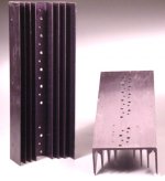
Also, I had bought these heatsinks for this project. Says they are for mounting 10 TO-3 transistors. I think there are eight per channel with this amp. Do these look large enough for the Leach Superamp?
Thanks, Terry
Also, I had bought these heatsinks for this project. Says they are for mounting 10 TO-3 transistors. I think there are eight per channel with this amp. Do these look large enough for the Leach Superamp?
Thanks, Terry
still4given said:I just set the bias according to Rod Elliot's directions. I'm not sure how to set the bias hotter without getting into trouble. I would be happy to try it with some instruction.
Says they are for mounting 10 TO-3 transistors. I think there are eight per channel with this amp. Do these look large enough for the Leach Superamp?
Thanks, Terry
The heatsinks will be around 0.4 degrees/watt.
What voltage does the transformer on the P101 have ?
Does Rod recommend a specific heatsink for the different amplifier
outputs ?
No point in paying for 2nd side copper that will be etched away.
You should do the basic math against the size of the heatsinks:
http://sound.westhost.com/heatsinks.htm
has a calculator that gives a conservative idea.
I seem to remember that Prof. Leach says about .67 degrees C/W for each heat sink on the Low TIM amp. Best check tho. The spacing on your heatsink is not really optimal.
This style from http://apexjr.com (not an endorsement, example only) is much better for even distribution of heat and for installing the diodes between the transistors.
What you already have may work OK, but if it was mine, I wouldn't use them.
Prosit
Attachments
jacco vermeulen said:
The heatsinks will be around 0.4 degrees/watt.
What voltage does the transformer on the P101 have ?
Does Rod recommend a specific heatsink for the different amplifier
outputs ?
This is how Rod suggests setting the bias on the P101.
Once you are sure that everything is in order, return the bias trimpot to the minimum resistance setting. Connect the amplifier to the main supply using the 100 ohm safety resistors. Apply power - again, the voltage across each 100Ù safety resistor should be between 2 and 3 volts. Carefully advance the bias pot until the voltage across each 100Ù resistor is 2V greater than your first measurement - this represents 20mA quiescent current in the MOSFET output stage.
I've heard of folks running higher bias to improve bass response. I would like to try that as the bass is a little on the light side. I just don't want to hurt anything.
The transformer I used in my P101 is a 45-0-45 which is giving me about +-65VDC rails.
Hi Ace,
I just received the heatsinks. They are too small for this project.🙁 I have some others that are larger but not well designed for TO-3 transistors. Are there equivalent transistors in a TO-264 or something like that?
I have two of these heatsinks.
I also have 4 of these heatsinks.
Thanks for all your help,
Terry
The "Large Aluminum Heat Sinks Allen Bradley" are probably more suited to the Superamp. However you will need to cut them in half for the heighth to make sense.
There are plastic transistors that you can use. Never used anything but T03's in my amps, so don't really know what the numbers are.
Prosit
There are plastic transistors that you can use. Never used anything but T03's in my amps, so don't really know what the numbers are.
Prosit
still4given said:
The transformer I used in my P101 is a 45-0-45 which is giving me about +-65VDC rails.
With regular AB amplifiers maximum dissipation occurs when the output has half of the rated powersupply voltage on it.
It is easy to proove with a differential equation but simple reasoning will give the same result.
With a lower output voltage the voltage loss is higher, but consequently the output current lower.
Vice versa, if the voltage on the output is higher, the voltage loss in the output transistors is lower but the current through the transistors will be higher.
Suppose the powersupply has 40 volts on it.
The load is 8 Ohms.
If there is no voltage on the amplifier output the voltage loss in the output devices is 40 Volts.
However, with no output voltage there is no current, the dissipation in the transistors will be Zero.
Suppose the output voltage is 40 Volts.
The output current will be 40 divided 8 Ohms, the current will be 5 Amps.
Again, because the voltage loss in the transistors is Zero volts, dissipation will be Zero.
With an output of 10 volts, the loss in the output stage will be 30 volts.
At 10 volts in 8 Ohm, the current will be 1.25 Amps.
Dissipation will be 30 Volts times 1.25 Amps = 37.5 Watts.
With 30 Volts output, voltage loss will be 10 Volts.
Current will be 30 / 8 = 3.75 Amps.
Again, dissipation will be 10 Volts loss times 3.75 Amps current, equals 37.5 Watts.
Now suppose the output voltage is half of the rated level, 20 Volts.
Current will be 20 / 8 = 2.5 Amps.
Dissipation becomes :
20 Volts loss in the output devices times 2.5 Amps current.
20 * 2.5 = 50 Watts.
For your amplifier voltage is 45 Volts, after rectification half of it is around 22 Volts.
Suppose the amplifier will be set up for a minimum of 4 Ohm loads which it will drive with maximum power.
Maximum dissipation becomes (22 * 22) / 4 = 121 Watts.
With 4 output devices rated at 150 watts the thermal factor for a transistor is 125 / 150 = 0.83.
Thermal resistance for the mica layer is around 0.50.
Suppose maximum heating of the transistors is limited to 100 degrees C.
With an ambient temperature of 25 degrees C it leaves a safety margin of 25 degrees, maximum die temperature is 150 degrees C.
1 transistor will dissipate 121 / 4 ~ 30 watts.
At 100 degrees over ambient total thermal resistance may not be larger than 100 / 30 = 3.33
Which leaves for the heatsink : 3.33 - 0.83 - 0.50 = 2 .
There are 4 transistors on the heatsink each claiming 1/4 th of the heatsink.
Maximum thermal resistance of the heatsink will be:
2 / 4 = 0.50 C/W
Suppose your heatsinks are 0.35 C/W
That is 70 % of the calculated one, at 30 degrees C over ambient the remaining 70 degrees margin will still be able to take 121 watts dissipation before the die of the transistors becomes 125 Degrees C.
Raising the temperature of a 0.35 C/W heatsink by 30 degrees over ambient means putting 85 watts in it constantly.
45 Volts continuous transformer Voltage is around 62 Volts peak after rectification.
85 divided 62 = 1.37 Amps.
1.37 Amps is around 7.50 Watts in Class A in a 8 Ohm load.
As half of the current goes through one output side bias in the output stage can be set to 0.34 Amps per output device.
To keep on the safe side you could set the bias to 5 Watts in Class A.
With average sensitivity loudspeakers of 88 dB at 1 watt, 5 watts is 7 dB higher, giving you Class A performance up to 95 dB soundpressure level.
5 watts in 8 Ohm is a bias of 0.56 amps.
Normal procedure is measuring voltage drop on the source resistors of the output device.
If you are using 0.22 Ohm source resistors bias is raised untill you measure 0.06 Volts drop over the resistor.
If you use Rod's method, replacing the fuse by a 100 Ohm resistor again and adjusting bias to 0.56 Amps will require a power resistor of minimum 32 watts.
( 0.56 Amps in 100 Ohm equals 56 Volts drop)
A safe way would be to raise bias in steps, going from the bias now to 0.20 Amps (0.64 watt)- 0.40 Amps(2.56 watt) till the maximum level, measure heatsink temperature at every step.
Hi Ace,
Thanks so much for the drawings. May I assume that the layout drawing needs to be reversed? It appears that it is the same side view as the foil.
Hi jacco,
Wow! That's a lot of info. Thanks for taking the time to type all of that. Scarey thing is that I was able to grasp a lot of what you wrote. Two months ago that would have been totally Greek to me. That's encouraging. 🙂
If I may, let me ask a couple of questions about setting the bias.
Do I understand you to say that to set the bias using Rod's method would require 100 ohm 32W resistors?
You mention 0.22 ohm source resistors. I'm not sure I know which ones those are. If you look here, you can see the schematic for the amp I built. It is Figure 2 - High Power Version. Am I correct is assuming that the source resistors would be R12, R13, R16 & R17? Those are 0.33 ohm. Is this where I would measure the voltage drop? Would that change the voltage drop I should see?
I don't mean to highjack this thread. Hopefully this information will transfer to this Leach amp as well, as that is what I plan to build next.
Thanks again, Terry
PS: The speakers I listen through mostly are JBL 4425, sensitivity (1W, 1m) 91dB SPL and 4412 sensitivity (1W, 1m) 90dB SPL.
Mornin Terry,
Ummm, depends on what method you use to put it on the copper.
With Press-n-Peel you want to see the image right reading.
Prosit
Ummm, depends on what method you use to put it on the copper.
With Press-n-Peel you want to see the image right reading.
Prosit
still4given said:Do I understand you to say that to set the bias using Rod's method would require 100 ohm 32W resistors?
Am I correct is assuming that the source resistors would be R12, R13, R16 & R17? Those are 0.33 ohm. Is this where I would measure the voltage drop? Would that change the voltage drop I should see?
Both correct.
The source resistors are the big green ones on the picture, the numbers you mention.
I think Mr Elliot mentions somewhere in his description that these resistors make sure the bias is divided equally between both output devices ( within twice the accuracy of the resistors).
The lower power amplifier only has one output transistor per side and does not require such resistors.
0.22 Ohm is the most common value for source resistors.
Source (or emitter) resistors raise the output impedance and thus lower the damping factor of a power amp.
With a higher number of output devices and consequently higher number of source resistors, and the lower the value of these resistors, influence on the damping factor is minimised.
0.22 would be the normal choice, Mr Elliott is very conservative with a lot of parameters, with most he reasons that enough is enough. Stability is a very important element in his designs.
The schematic of the amplifier does not have the values printed, i did not bother to read the color lines on the pic.
At 0.33 Ohms and the same bias voltage drop over the source resistors becomes 1.5 times as high, 0.06 * 1.5 = 0.09 Volts
If you put the bias at 0.56 Amps going through a 100 Ohm resistor it will dissipate over 31 watts.
Voltage drop over the resistor will be 56 volts, not much left behind it.
Suppose you use a 4 Ohm resistor in place of the fuses.
At 0.56 amps you will read 2.24 Volts higher over the resistor than the reading for the currents for the front end stages.
With 4 ohms the first reading would be something like
0.08 to 0.12 volts
Dissipation in the resistor would be a little over 1.25 watts, a 2 watt resistor would do.
jacco vermeulen said:
Both correct.
The source resistors are the big green ones on the picture, the numbers you mention.
I think Mr Elliot mentions somewhere in his description that these resistors make sure the bias is divided equally between both output devices ( within twice the accuracy of the resistors).
The lower power amplifier only has one output transistor per side and does not require such resistors.
0.22 Ohm is the most common value for source resistors.
Source (or emitter) resistors raise the output impedance and thus lower the damping factor of a power amp.
With a higher number of output devices and consequently higher number of source resistors, and the lower the value of these resistors, influence on the damping factor is minimised.
0.22 would be the normal choice, Mr Elliott is very conservative with a lot of parameters, with most he reasons that enough is enough. Stability is a very important element in his designs.
The schematic of the amplifier does not have the values printed, i did not bother to read the color lines on the pic.
At 0.33 Ohms and the same bias voltage drop over the source resistors becomes 1.5 times as high, 0.06 * 1.5 = 0.09 Volts
If you put the bias at 0.56 Amps going through a 100 Ohm resistor it will dissipate over 31 watts.
Voltage drop over the resistor will be 56 volts, not much left behind it.
Suppose you use a 4 Ohm resistor in place of the fuses.
At 0.56 amps you will read 2.24 Volts higher over the resistor than the reading for the currents for the front end stages.
With 4 ohms the first reading would be something like
0.08 to 0.12 volts
Dissipation in the resistor would be a little over 1.25 watts, a 2 watt resistor would do.
Hi jacco,
Yes, I knew that the schematic didn't show the value, that's why I listed it. The value is in the BOM and the schematic in the construction docs but they are on a secure page. I figured he probably wouldn't like me posting that schematic.
You lost me a bit. Are you saying that I can't set the bias by measuring across R12, R13, R16 or R17?
Are you suggesting that I use Rod's method, except with a 4ohm 2 watt resistor?
Thanks again, Terry
I am saying you can do both.
The most accurate is measuring voltage over one of the resistors you mentioned; R12,R13,R16,R17.
You can do it Mr Elliott's way but you will need a high power resistor if you go for 100 Ohms or the resistor will melt while biasing.
Mr Elliott has a sense of humor.
A lot of his designs do not have that many parts.
He lists the active ones in his schematics, the passive are either standard values or can be read from the high resolution pictures he presents with his projects.
For those that absolutely have a thing for doing it all themselves he seems to offer a challenge.
Leach clone
Hey Thanks alot guys.I decided i will just make my own boards here at the Hotel I will be in for 4 months.I dont really need that much stuff . My enclosure wont be anything more then a box but I can fix that when I get home.Probably get arrested cause they will think I got a meth lab set up or something.WHats the dif between a superamp or plain leach amp ? Which is better ?I am not looking for power , I want clean sound .I was a jet engine mech for 10 years so loud isnt my thing anymore.Is photo etching better or peel and print. Any one ever just draw by had and photo etch .Frye's here has light for 22.00 with stand and has mostly sensitized boards.
Hey Thanks alot guys.I decided i will just make my own boards here at the Hotel I will be in for 4 months.I dont really need that much stuff . My enclosure wont be anything more then a box but I can fix that when I get home.Probably get arrested cause they will think I got a meth lab set up or something.WHats the dif between a superamp or plain leach amp ? Which is better ?I am not looking for power , I want clean sound .I was a jet engine mech for 10 years so loud isnt my thing anymore.Is photo etching better or peel and print. Any one ever just draw by had and photo etch .Frye's here has light for 22.00 with stand and has mostly sensitized boards.
dherr555,
The Low TIM Leach amp as described in the doc's:
http://users.ece.gatech.edu/~mleach/lowtim/
will produce 120W of very clean music power.
The Superamp, given enough voltage will produce 300W+ with a higher parts count. But it is mostly the same amp.
In a hotel room Press-n-Peel is definately easier.
Prosit
- Status
- Not open for further replies.
- Home
- Amplifiers
- Solid State
- Leach clone, pretty good looking