Vesa said:Here (see attachment) is the reason, why I asked about "missing" layout.
But yes. There is picture after all. Right click -> wiew image. I dont' know if some "wiewer" missing of my PC, or why it's not wisible.
Sorry about my nonsense 🙁
Let's build some amps
-Vesa-
Hmmmm.....
That's odd. Both images are just run-of-the-mill GIF images, but they are quite large. If you have a dialup connection it may take a while to download.
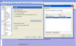
Do you not have Mozilla set to automatically display images? Go to Edit > Preferences > Privacy & Security > Images. Select "Accept all images" under Image Acceptance Policy. Also click on "Manage Image Permissions" to make sure that you aren't blocking any sites unintentionally.
You have probably made it by mistake like I did. Do you ever right-click? Maybe you have missed once and hit "block images from this server"?
peranders said:Do you ever right-click? Maybe you have missed once and hit "block images from this server"?
Now I remember. Probable that's just what were happened.
Re: Transistors
Hi Jens,
Do you think the MJL4281 is superior to the MJL 3281?
Do you have an idea of when the PCB's will be ready?
Thanks, Terry
JensRasmussen said:If you have these transistors available, I don’t see any reason for not using them.
I plan to use either MJL3281/1302 or their newer bigger replacements MJL4281/4302.
\Jens
Hi Jens,
Do you think the MJL4281 is superior to the MJL 3281?
Do you have an idea of when the PCB's will be ready?
Thanks, Terry
Hello Terry,
I don’t really think there is any difference in performance in the voltage range I plan to use the transistors. I hope to be driving my amps at +- 68V or around that depending on what transformers I can get my hands on.
The boards will arrive in mid February and then I’ll need some time to do testing. I'm really busy at work at the moment, so bare with me if I’ll be slow with the updates. I will post pictures and other information when I get the time.
\Jens
I was planning on using my 62-0-62 toroid for this. That would be aprox 87V rails. Will that work with your design? This is the main reason I was looking at the Leach Superamp. Someone told me it could run at those voltages.
Thanks, Terry
Thanks, Terry
Member
Joined 2002
I'm wondering on any one's thoughts are on the leach amp the 4 transister one or the 10 are they good for sub amps i only need a few watts like 100 or so decent ?
Hello Terry,
I have simulated the circuit using 75 V rails. However I have not tested it in real life.
I think that the Leach super amp is a result of output devises at the time of construction seldom could be used at more than perhaps 120 – 160V thus the need for an output ladder.
I like the superamp too, and might make a layout for that sometime.... 😉
\Jens
Yo jleaman and still4given,
My Leach amp has been driving a pair of 12" active crossover subs for more than 10 years. Only modification was to increase the bias to 125 for a bit more low end.
My Leach super amp runs quite happily on 93V rails producing 300W.
But can honestly say that listening to it in a 900 square foot room at 62 Watts will make your ears ring for hours. Caps that will handle this voltage are not cheap.
Prosit
I think that the Leach super amp is a result of output devises at the time of construction seldom could be used at more than perhaps 120 – 160V thus the need for an output ladder.
I like the superamp too, and might make a layout for that sometime....
Huh, for some reason, I was under the impression that your board is a super amp design. Rats!

Sorry for all the trouble. I should have paid better attention.
 Do you know of anyone making boards for the Superamp?
Thanks, Terry
acenovelty said:Yo jleaman and still4given,
My Leach amp has been driving a pair of 12" active crossover subs for more than 10 years. Only modification was to increase the bias to 125 for a bit more low end.
My Leach super amp runs quite happily on 93V rails producing 300W.
But can honestly say that listening to it in a 900 square foot room at 62 Watts will make your ears ring for hours. Caps that will handle this voltage are not cheap.
Prosit
Hi Prosit,
I guess we were typing at the same time.
Did you make your own boards for the superamp or do you know someone who is now making them? I have no experience making PCB's and I would hate to go to the expense of building this amp and have it fail because I messed up the boards.
Any help will be greatly appreciated.
Blessings, Terry
Mornin Terry,
Made my own boards using Press-n-Peel Blue Transfer Film from:
http://www.techniks.com/
Short tutorial:
http://www.techniks.com/how_to.htm
You would also need: laser printer/copier, copper clad printed circuit board material, drill bits, drill press, ferric chloride and a good measure of patience.
Never found anyone producing drawings of any kind or PCB's for sale.
My old drawings are simple bitmap images. If you want to go to the effort to learn this stuff, I'll dig them out.
Prosit
Thanks Prosit,
I guess I had better learn how to make PCB's if I'm going to be able to have much success in the DIY field. No time like the present.
I will look into the techniks stuff. Did you use the PCB layout from the Leach Double Barrel website?
http://users.ece.gatech.edu/~mleach/superamp/
I have printed that out. Looks pretty simple.
Thanks again for the offer to help.
Blessings, Terry
Hi Terry,
Used it as a starting point. That layout works just fine, but did not suit my chassis for wiring the power transistors easily. And I used many caps/resistors that were better and not the same physical size as in the layout. So, many changes from what you are seeing. First time out, it might be better to follow Prof. Leach's board.
There are many common elements to both versions. Might be a good idea to download everything and print it out for reference. When I built the first Superamp board following the destruction manual exactly, it worked the first time.
Press-n-peel is so good that you should have to sacrifice only one set to get it right the second time. Much better than UV light on sensitized boards from film tracings.
Prosit
acenovelty said:Hi Terry,
Used it as a starting point. That layout works just fine, but did not suit my chassis for wiring the power transistors easily. And I used many caps/resistors that were better and not the same physical size as in the layout. So, many changes from what you are seeing. First time out, it might be better to follow Prof. Leach's board.
There are many common elements to both versions. Might be a good idea to download everything and print it out for reference. When I built the first Superamp board following the destruction manual exactly, it worked the first time.
Press-n-peel is so good that you should have to sacrifice only one set to get it right the second time. Much better than UV light on sensitized boards from film tracings.
Prosit
Hi Prosit,
When you say "There are many common elements to both versions", what two versions are you referring to? Is there a PCB layout for the second one you refer to? IF there is an upgrade to the original, I would rather build that one.
On the press-n-peel, did you just use an iron or did you buy the press? IF I'm going to do this, I want to do it right.
Thanks again,
Terry
The press-and-peel stuff i tried some 15y ago, the first one introduced here was called TEC2000
(not exactly sure about the 2000, blame my age )
)
I blew more than a package of the stuff before getting one fairly decent pcb. Even then the lines were either too thin, or too wide.
Maybe the foil has been dramatically improved in a decade and a half, i got me a UV-suitcase and an etching device and that works just fine.
Should the p-and-p thing not be to your satisfactory, i can make you a couple of boards if you have a decent layout, Terry.
(not exactly sure about the 2000, blame my age
)I blew more than a package of the stuff before getting one fairly decent pcb. Even then the lines were either too thin, or too wide.
Maybe the foil has been dramatically improved in a decade and a half, i got me a UV-suitcase and an etching device and that works just fine.
Should the p-and-p thing not be to your satisfactory, i can make you a couple of boards if you have a decent layout, Terry.
Hi Terry-
I have used the photo-sensitive method many times. It is quite easy. Though there are many kits that make it even easier, all you really need is an inkjet printer, some inkjet compatible overhead film (Staples), a piece of glass and a florecent light.
Print out the foil pattern on the film. Use a Sharpy-type black pen to be sure it is clean (cover any bare-looking spots). Lay the film on the photo-sens boards, lay the glass on to hold it down, and expose it with the flor light (boards will come with recommened times).
Boards and developer are available from many places (Digi-Key, PartsExpress etc). I think the developer is about $2US per bottle, and mixes 1-10 with water. after developing, you will see the image of your traces on the pc board. Again use the sharpy to be sure everything you want to stay on the board is there.
Then etch away. Tupperware makes a good etching tank, and you can seal it up for later use. Etching works faster when heated - I use a flood lamp help over te tupperware while I gently rock it. Use ventalation or a resperator. You can do it with for small board, but I am not recommending it officially.
I also find it works best to have a beer open for sipping while you etch. It can take a little while, but you must stay on top of it.
Rinse with water and you are done.
There are some tinning solution products out there, but I have never tried them and have read some bad things about them. I tin by hand with a soldering iron. If there are any gaps in your traces, there are a multitude of ways to fix them, but I have never had to do so with the photo boards.
-b
- Status
- Not open for further replies.
- Home
- Amplifiers
- Solid State
- Leach clone, pretty good looking