Hello all, I want to build the leach amp.I followed a link of his sight to a PCB maker.I am gonna draw up a pcb and order some.The prices dont look to bad .Just the the first one.When I am done I will post prices and get some extras if anyone is interested.Really fast turn around too.Not sure how long it will take to draw out wiring.I was gonna copy his layout .Looks like it will around 20.00 per channel after the first ones. its a pain trying to find some of the older parts.Anyone find a good supplier for the xformer yet.
When you say you are going to build the Leach amp, which one are you refering to? Superamp? If so, I might be interested in the PCB's. Keep us posted please.
Blessings, Terry
Blessings, Terry
WorkingAtHome said:Hi Terry-
I have used the photo-sensitive method many times. It is quite easy. Though there are many kits that make it even easier, all you really need is an inkjet printer, some inkjet compatible overhead film (Staples), a piece of glass and a florecent light.
Print out the foil pattern on the film. Use a Sharpy-type black pen to be sure it is clean (cover any bare-looking spots). Lay the film on the photo-sens boards, lay the glass on to hold it down, and expose it with the flor light (boards will come with recommened times).
Boards and developer are available from many places (Digi-Key, PartsExpress etc). I think the developer is about $2US per bottle, and mixes 1-10 with water. after developing, you will see the image of your traces on the pc board. Again use the sharpy to be sure everything you want to stay on the board is there.
Then etch away. Tupperware makes a good etching tank, and you can seal it up for later use. Etching works faster when heated - I use a flood lamp help over te tupperware while I gently rock it. Use ventalation or a resperator. You can do it with for small board, but I am not recommending it officially.
I also find it works best to have a beer open for sipping while you etch. It can take a little while, but you must stay on top of it.
Rinse with water and you are done.
There are some tinning solution products out there, but I have never tried them and have read some bad things about them. I tin by hand with a soldering iron. If there are any gaps in your traces, there are a multitude of ways to fix them, but I have never had to do so with the photo boards.
-b
Hi Workingathome,
So you think the photo- sensitive boards are easier than the p-n-p method? You mention kits. Link?
Thanks, Terry
Hi Terry,
Seems you started a bunch of questions and comments.
So here goes:
There are two versions of the leach amp Published by Prof Leach. The Low TIM http://users.ece.gatech.edu/~mleach/lowtim/ and the Superamp or Double Barrelled Amplifier http://users.ece.gatech.edu/~mleach/superamp/
Yes "the layout on this page" is "good enough to make a pcb", I modified it to serve my case layout, parts choice. There must be many variations of this layout given the number of students who have to build it to pass his course material.
The two versions are very similar in layout and parts used. Therefore the destruction manual applies to both versions with modifications.
The Press_n_Peel Blue is not the old product that many of us had problems with in the past. Having used all the other mentioned systems and being so old that I actually hand coated the emulsion onto the copper, made reverse films, built my own UV exposure box w/timer and then developed the board in years past, it is my opinion that the current product by http://www.techniks.com/ is the most simple, least expensive in time and money and forgiving method. Traces as small as 1/32" work just fine on .5 mil copper bonded to .5mil Kapton film. That is not to say some care and diligence is not required.
Refer to the FAQ's http://www.techniks.com/pnp_faq.htm
You don't learn anything from doing it right the first time. Did anyone mention this can be an expensive hobby?
And yes I used an ordinary iron. Tho it does have a large platen.
You can make a larger platen for any iron by attaching a larger sheet of 1/8" copper sheet to the base. Now you have a square or rectangel shape to your choice. Just let the entire base reach an even temperature.
These guys make transformers specifically for the leach amp.
http://www.victoriamagnetics.com/
taken from the Leach web site.
None of the parts are particularly older/hard to find and many can be had as free samples from
http://www.onsemi.com/
Most everything else available from http://www.digikey.com/
or the locations listed on the Leach web site under the heading:
Parts List and List of Suppliers.
RIF
The most difficult part of building the Leach amp is setting the bias current.
Some modest observations about the Superamp on speakers that I built to take the power. You can't play it much louder than half its ability without hurting yourself. And no distortion. It will drive a pair of subwoofers beyond your needs. It will drive most any speaker you attach it to without problems, except for the temptation to keep turning it up and causing ringing of the ears.
So build it with confidence and enjoy.
Prosit
Seems you started a bunch of questions and comments.
So here goes:
There are two versions of the leach amp Published by Prof Leach. The Low TIM http://users.ece.gatech.edu/~mleach/lowtim/ and the Superamp or Double Barrelled Amplifier http://users.ece.gatech.edu/~mleach/superamp/
Yes "the layout on this page" is "good enough to make a pcb", I modified it to serve my case layout, parts choice. There must be many variations of this layout given the number of students who have to build it to pass his course material.
The two versions are very similar in layout and parts used. Therefore the destruction manual applies to both versions with modifications.
The Press_n_Peel Blue is not the old product that many of us had problems with in the past. Having used all the other mentioned systems and being so old
that I actually hand coated the emulsion onto the copper, made reverse films, built my own UV exposure box w/timer and then developed the board in years past, it is my opinion that the current product by http://www.techniks.com/ is the most simple, least expensive in time and money and forgiving method. Traces as small as 1/32" work just fine on .5 mil copper bonded to .5mil Kapton film. That is not to say some care and diligence is not required.Refer to the FAQ's http://www.techniks.com/pnp_faq.htm
You don't learn anything from doing it right the first time. Did anyone mention this can be an expensive hobby?
And yes I used an ordinary iron. Tho it does have a large platen.
You can make a larger platen for any iron by attaching a larger sheet of 1/8" copper sheet to the base. Now you have a square or rectangel shape to your choice. Just let the entire base reach an even temperature.
These guys make transformers specifically for the leach amp.
http://www.victoriamagnetics.com/
taken from the Leach web site.
None of the parts are particularly older/hard to find and many can be had as free samples from
http://www.onsemi.com/
Most everything else available from http://www.digikey.com/
or the locations listed on the Leach web site under the heading:
Parts List and List of Suppliers.
RIF
The most difficult part of building the Leach amp is setting the bias current.
Some modest observations about the Superamp on speakers that I built to take the power. You can't play it much louder than half its ability without hurting yourself. And no distortion. It will drive a pair of subwoofers beyond your needs. It will drive most any speaker you attach it to without problems, except for the temptation to keep turning it up and causing ringing of the ears.
So build it with confidence and enjoy.
Prosit
Hi-
I have not tried the Blue film. Just mentioning my experience with the photo-etching process. Since I am hearing a lot of good things about it, I will have to give it a shot. Non-photo PCB's are WAY cheaper, so it may be a better method, though I don;t have a laser printer (could just do it at work).
It actually reminded me of an old toner-based system we used for a little while to make offset lithography plates, and made me cringe. That was a LONG time ago though, and has no conection with rational decision making.
Hmmm. All this talk, and I just ordered photo boards for my Leach boards (again custom designed for my chassis) the other day. How does that keep happening... ;-)
-b
Check out the prototypeing section of the Digikey online catalog, in particular, pages 1319-1321.
http://dkc3.digikey.com/PDF/T051/SectJ.pdf
http://dkc3.digikey.com/PDF/T051/SectJ.pdf
leach amp pcb
I Have not decided on the low tim or super amp yet .Before I do a pcb I am trying to find some large caps and xformer. The pcb they have is a little small and doesnt leave much room for heat sinks on transistors.They say they arent needed but I would prefer they had some just to be sure I dont have any thermal problems.Having to redo pcb would be costly .Any Ideas on layout ?I am open to suggestions because it would help lower my costs if I got some extras that other people would want. I want to build a 3 channel.I cant decide if I should go with 1 channel per board or have a larger one with all.I have also seen an amp done with the outputs on the pcb with sinks instead of the large vertical ones.They said they had no problem with heating.
I Have not decided on the low tim or super amp yet .Before I do a pcb I am trying to find some large caps and xformer. The pcb they have is a little small and doesnt leave much room for heat sinks on transistors.They say they arent needed but I would prefer they had some just to be sure I dont have any thermal problems.Having to redo pcb would be costly .Any Ideas on layout ?I am open to suggestions because it would help lower my costs if I got some extras that other people would want. I want to build a 3 channel.I cant decide if I should go with 1 channel per board or have a larger one with all.I have also seen an amp done with the outputs on the pcb with sinks instead of the large vertical ones.They said they had no problem with heating.
still4given said:Would the layout on this page be good enough to make a pcb from?
Its up to you.
In my view it is substandard, had it not been symmetrical i would take it for a layout made with rub-on tape.
The output devices are not on the pcb, meaning that they need to be wired from the board.
Many regard this as a risk: it may create humming or even turn the amplifier in oscillation.
My fee is 1 package of 20 NO FILTER
 genuine American Camel cigarettes.
output on board
Thats what I was talking about .I was thinking of doing a pcb with the outputs on the board.This will make a much larger board with the cost going way up.I am on the road for 4 months so I cant make my own.It would be a pain for me to try and drill without a press(which would be no fun too).Shoulds I try a board with 2 channels on one or 1 channel each. I want to use screw type caps for filters or would large board ones work okay.Would it be good to put rectifier and those caps on there own boards.I am going to use 4 caps per channel.I want to put three channels in a box but this may be to large of an enclosure.Any suggjestions ?
Thats what I was talking about .I was thinking of doing a pcb with the outputs on the board.This will make a much larger board with the cost going way up.I am on the road for 4 months so I cant make my own.It would be a pain for me to try and drill without a press(which would be no fun too).Shoulds I try a board with 2 channels on one or 1 channel each. I want to use screw type caps for filters or would large board ones work okay.Would it be good to put rectifier and those caps on there own boards.I am going to use 4 caps per channel.I want to put three channels in a box but this may be to large of an enclosure.Any suggjestions ?
THANK YOU ACE
Forgot to say thank you for links and info.Its gonna take me a week or so to decide on an enlcosure size and number of channels per enclosure.I want to make enough to run a 6.1 or 7.1 setup. Would be easier and cheaper to just buy a 7.1 amp but wheres the fun in that.
Forgot to say thank you for links and info.Its gonna take me a week or so to decide on an enlcosure size and number of channels per enclosure.I want to make enough to run a 6.1 or 7.1 setup. Would be easier and cheaper to just buy a 7.1 amp but wheres the fun in that.
OK folks,
"The output devices are not on the pcb, meaning that they need to be wired from the board."
This is why I redesigned the layout for my case.
"Many regard this as a risk: it may create humming or even turn the amplifier in oscillation."
Prof. Leach cautions about this issue in the destructions. Never experienced the problem myself. Only built a half dozen or so of his amps, tho.
Try this guy's solution.
Website:
http://home.swipnet.se/malman/LeachAmp.html
Picture:
http://home.swipnet.se/malman/lowtim_circuitboard.jpg
dherr555
"The pcb they have is a little small and doesnt leave much room for heat sinks on transistors."
Proper sized heatsinks are readily available for this purpose.
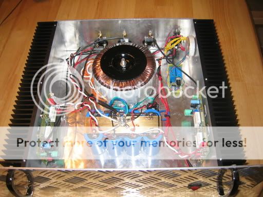
One stereo amp fits nicely in a 6"Hx17"Wx15"D box.
BTW, if you put the recommended resistors across the caps, there are NO turn on or turn off noises. Also in the doc's, you may learn that if a transistor dies in this amp, you do not destroy your valuable speakers.
"The output devices are not on the pcb, meaning that they need to be wired from the board."
This is why I redesigned the layout for my case.
"Many regard this as a risk: it may create humming or even turn the amplifier in oscillation."
Prof. Leach cautions about this issue in the destructions. Never experienced the problem myself. Only built a half dozen or so of his amps, tho.
Try this guy's solution.
Website:
http://home.swipnet.se/malman/LeachAmp.html
Picture:
http://home.swipnet.se/malman/lowtim_circuitboard.jpg
dherr555
"The pcb they have is a little small and doesnt leave much room for heat sinks on transistors."
Proper sized heatsinks are readily available for this purpose.
One stereo amp fits nicely in a 6"Hx17"Wx15"D box.
BTW, if you put the recommended resistors across the caps, there are NO turn on or turn off noises. Also in the doc's, you may learn that if a transistor dies in this amp, you do not destroy your valuable speakers.
Hi Ace,
You say you built a half dozen? Were those with his design or yours? I already have a few heatsinks that I hope to use for this amp. Did the heatsinks run hot on the amps you built?
I bought large heatsinks for the ESP P101 amp I built only to find that it barely gets warm, even at ear-bleed levels.
It the construction details he says you need seperate heatsinks for the PNP & NPN output Transistors. Do you know what the reason for that is? That makes the case a little harder to build. Not a big deal if it's important. I just don't understand the logic.
Thanks Terry
PS, Did you say you might have the layout for your design? Sure like to take a look at that. 😀
Blessings
I've built several Leach amps over the years with outputs
wired some six inches away from the board, with no
obvious stability problems or hum. Despite the necessary
rat's nest of wiring, the design seems very stable. I do
recommend plenty of heat sink area and good ventilation;
thermal runaway was never a problem for me, but I've got
enough bias on that the heatsinks get fairly warm at idle.
Sustained high power output into my inefficient AR-11s gets
pretty toasty.
I've recently put together a channel using one of Brian
Bell's boards with MJL21193/4 plastic case transistors
soldered directly to the board. It eliminates a lot of wiring,
looks better, and possibly benefits by shortening the path
of the feedback loop--one of the claimed benefits of the
GainClones. I dunno. I haven't had an opportunity to listen
to this version of the amplifier and I may have wired in a
mistake in the protection circuit.
I see where some layouts have been done directly wiring
TO-3 devices to the boards, and that should be good, too.
My Ultimate Leach Amplifier may use Brian's or Jen's board
in a new chassis and using premium parts throughout. But
my current amplifier using the 4.5 version board sounds very
good, so I'm not in much of a hurry to spend the money.
Hi Terry,
Built the first one according to the original Low TIM as a test. After that I changed the layout for all the other amps. I did not use the heatsinks he recommends in the parts list. They are about 6''Hx15"L W 2" fins and run warm partly cause the bias is set to 125 for a bit more bass. They never run hot.
"seperate heatsinks for the PNP & NPN output Transistors"?
Haven't been able to find a reference to this with a cursurory glance thru the doc's. However since the parts list refers to Q18 - Q21, which are the output transistors and they are mounted on the same heatink
as described in the Drilling the Heat Sinks section of "Construction Details", I hope you can find this info. I know of no one who has done it otherwise. I certainly did not mount them separate.
I have a bitmap drawing of the layout and parts placement. It is on another computer and I will need to dig it out of those files. Sorry that's not possible just now, but I will get them to you soon.
This is also a good solution:
Prosit
Attachments
Thanks guys,
I'll have to look for that reference to the weperate heatsinks. I'm sure I read it but I may be confused as to where it refered to.
I'll get back to you tomorrow.
Blessings, Terry
I'll have to look for that reference to the weperate heatsinks. I'm sure I read it but I may be confused as to where it refered to.
I'll get back to you tomorrow.
Blessings, Terry
A commercial version of the Leach amplifer was built with the
NPN and PNP transistors on separate heatsinks. It worked,
but it's not recommended practice.
(I worked for the company, briefly; that was Electronics One, Inc.,
in Atlanta, waybackwhen in the 70s I guess. I still have some
documentation and artwork for that amplifier. It existed in at
least two physically different versions; the latter version had
the separate heatsinks.)
Hi Terry,
The bitmap files are much too large to post here.
I can sent them to you private if you wish.
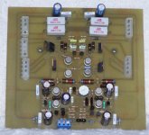
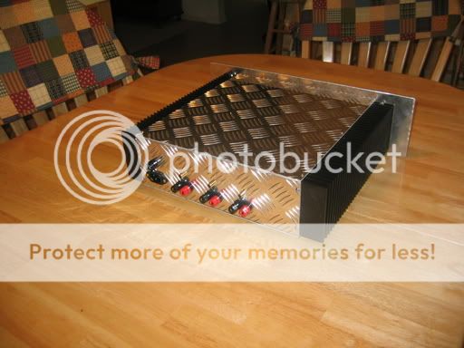
The final boards are in the amp mounted in a rack not so easy to get photos.
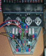
Pic of the prototype board for the Superamp.
I used computer power connectors to clean up the wiring rats nest.
The bitmap files are much too large to post here.
I can sent them to you private if you wish.
The final boards are in the amp mounted in a rack not so easy to get photos.
Pic of the prototype board for the Superamp.
I used computer power connectors to clean up the wiring rats nest.
Attachments
leach amp pcb
Thank you , I guess I will not try and fix whats not broken and go with two per enclosure and use outputs on external syncs ,they can look cool on the back.i wanted to keep it in two enclosusers for 6 channels and only buy two xformers.But I think that would be a little cluttered and get toasty in one enclosure anyway.Plus I am getting old and it would probably wiegh a ton. I like those boards using computer connectors , what gauge wire did you use to go to outputs.Do you mind if I use a similiar layout for my boards ? I should have time to draw some up this week and order some.I dont enough stuff with me to etch my own.I will probably have ten made when I do because that wont be much more then the 6 I want.I will post pictures when I get them and sell them for what they cost me and shipping when I get them .I am gonna go unmasked and no screen because its almost half the price that way .Or should I spend the extra cash.Should be around 200 - 220 for 10 or like 280 withmask and screen.Not sure if they charge extra for drilling , probably do so I wont get a real idea till make them up.I dont have any software so I am gonna use expresspcb or another like them . I cant find anyone that takes gerbers that I got on the web.The couple I found want stupid money for such a small board.
Thank you , I guess I will not try and fix whats not broken and go with two per enclosure and use outputs on external syncs ,they can look cool on the back.i wanted to keep it in two enclosusers for 6 channels and only buy two xformers.But I think that would be a little cluttered and get toasty in one enclosure anyway.Plus I am getting old and it would probably wiegh a ton. I like those boards using computer connectors , what gauge wire did you use to go to outputs.Do you mind if I use a similiar layout for my boards ? I should have time to draw some up this week and order some.I dont enough stuff with me to etch my own.I will probably have ten made when I do because that wont be much more then the 6 I want.I will post pictures when I get them and sell them for what they cost me and shipping when I get them .I am gonna go unmasked and no screen because its almost half the price that way .Or should I spend the extra cash.Should be around 200 - 220 for 10 or like 280 withmask and screen.Not sure if they charge extra for drilling , probably do so I wont get a real idea till make them up.I dont have any software so I am gonna use expresspcb or another like them . I cant find anyone that takes gerbers that I got on the web.The couple I found want stupid money for such a small board.
Hi,
cut your board costs by putting 2 channels on the same board & then sawing them apart after delivery.
How about including another section for your DC block and soft start & then there's the PSU. Just try & get the join lines straight to suit the sawing.
Regards Andrew T.
cut your board costs by putting 2 channels on the same board & then sawing them apart after delivery.
How about including another section for your DC block and soft start & then there's the PSU. Just try & get the join lines straight to suit the sawing.
Regards Andrew T.
OK, I found the reference. It's under "Circuit Description" and it states "Because there are eight output transistors, two main heat sinks per channel are required. Q18, Q20, Q28, and Q30 should be mounted on one and Q19, Q21, Q29, and Q31 on the other. "
I just didn't know if there was an electronic reason for this or just a physical reason.
Hi Ace,
I would love to see those bitmaps if you don't mind.
still4given@yahoo.com
Did you make a drawing for the foil traces? How did you make your boards? That's a cool idea using the computer connectors. Really make for a clean board.
Hi Damon,
Thanks for the info on the heatsinks. I was hoping to just use two large heatsinks for my amp. I didn't want the case to get too large. The ESP P101 I built, ended up larger than I wanted. It will be alright once mounted in a rack, but it doesn't stack very well with my other amps.
Blessings, Terry
- Status
- Not open for further replies.
- Home
- Amplifiers
- Solid State
- Leach clone, pretty good looking