Mechanical hum
Hi Jens,
re post 254;
could that mechanical hum be due to DC passing through the primary?
Have you tried a DC block yet?
Pumping 500w? 2 channels @ 260w divided by efficiency, indicates about 800va (getting close to your 1kva)
Go on, find a way to do 4R and 3R testing - please.
Could you submerge the power resistors in a bath of cooking oil?
While your at it you could volunteer to use the power to make dinner tonight. Earn a few points, it may help later!
mikeks said:..not sure your choosen SOA protection permits efficient use of available SOA from your bank of output devices...
5 pairs can be persuaded to drive 4ohms<60deg. to nominal 55V rails....
With a triple slope SOA protection locus derated to roughly Tc~70deg., (or ~140W;adequate heatsink assumed), you could drive 4ohms<60deg., or even a 1ohm load to the supply rails without invoking protection.....no sweat...
..and..yes..i've examined your manual...

Hi,
The load lines in the manual are absolute worst case. They allow 2xVcc Vce on the output.
There is no protection curcuit in the manual.......yet 😉
\Jens
JensRasmussen said:
Hi,
The load lines in the manual are absolute worst case. They allow 2xVcc Vce on the output.
There is no protection curcuit in the manual.......yet 😉
\Jens
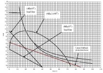
Actually, your loadlines (e.g fig4-11) do not represent the worst-case 4ohm reactive load....This is an error i believe originated sometime in 1970-72WW.
Easy to prove: Just plot a 4ohm<60deg load line (an ellipse actually) and superimpose it on your fig 4-11....
You'll find it falls way beyond your 'worst-case' 4ohm projection...Try 4ohm<45deg as well...
see below:
Attachments
mikeks,
Nice graph, what does it show?
Peak values, RMS values and what is the graph based on square waves or sine waves?
I have been looking for literature that describes how to make the graph at different impedance loads, but so far I have been unable to find anything else than the DC load lines I have already presented. There are plenty of application notes that mention the 45-degree load line as worst case, but none of the papers I have found actually explain how they arrive at a given graph.
If you have information, please post it…. I want to offer the best documentation that I can find. SO far I have used info found in Self’s and Sloan’s books.
\Jens
Jens
I was just having a look at the qsc 2450 schematic where they are using 4 pairs of PNP NPNs per channel (2SA1943 2SC5200 toshibas). They run them at 100v per rail with no problems. The amp delivers a massive 1200w at 2 ohms.
If this can run at such high voltages I dont see why the extended leach cannot, which uses exactly the same drivers and similar power transistors with an added pair of transitors. It appears that using forced cooling an amp can deliver easily 400w at 8ohms.
I guess the only difference is that the qsc is a class H amp with modulated PSU voltage.
While talking about modulated PSU's the Sunfire power amp (used the older and less rated c3281/a1302) was rated at 300w into 8 ohms, 1200 into 2 ohms and 2400 into 1 ohm. I am not sure how many pairs it had but I think it was not more than 4-6 pairs.
However the issue is on that amplifier, the supply rails kept only 6v above the voltage needed to output the waveform, so the trannies were virtually working on +/-6vdc rails. At that voltage, those trannies can output the full 15amps each device. As the signal strength rose, the rails would rise as well still leaving only 6 volts to dissipate the amps. The worst case scenario was 15amps at 6 volts = 90 watts per transistor. Bob also has a Signature version with the exact same design and output section but this one was rated 600 watts into 8 ohms, and 2400watts into 2 ohms (not rated for 1 ohm like the other). This thing used NO heatsinks. The trannies were mounted on to the body of the amp.
Unfortunately the same does not hold true for class-A-AB amps.
Class-H is in the middle somewhere and so is class-G when it comes to efficiency. In the order of efficiency (from worst to best as far as I know)
A
AB
B
C
G
H
Sunfire (switching power supply)
D
jacco vermeulen said:Thanks for the chat, Jens.
Forgot to ask you if you ever saw the site from a company in one of the former easterblock countries that sells toroids for very low prices, even huge ones ?
I'd have to look on my explorer fav. list for the name.
Jacco, are you referring to Rockna electronics? they quoted me nice prices but I was suspect of sending my money to a Romanian manufacturer that no one had tried before....
K-
Yep, this one:
http://www.rockna-line.com/toroids.htm
I'd like a couple of them biggies.
I was thinking now that we have a Romanian stiff on one of the threads he might be able to check Rockna's MO.
If you count class C radio amplifiers you might as well include class F microwaves as well.
What is the max power rating of a ribbon tweeter ?
class H does sound v good though, in comparison with a number of other amps when used with a good pre.
Hi,
That was compairing , A class H amp with 4pairs of OP devices can deliver more power than a class AB amp with 10pairs of OP devices
That was compairing , A class H amp with 4pairs of OP devices can deliver more power than a class AB amp with 10pairs of OP devices
Can anyone tell me a recommend power supply for a 3 pair version? Like 2x40/45/50VAC and the R26, R34, R68, R69 and R41, R42, R43, R60, R61, R62, R28, R30 values?
Im driving 8 Ohm loudspeakers (but might replace them later)
Thanks in advance
Im driving 8 Ohm loudspeakers (but might replace them later)
Thanks in advance
3pair on 40Vac+40Vac.
My 40+40Vac gives +-58Vdc and 170W into 8r0 just before visible clipping.
My 40+40Vac gives +-58Vdc and 170W into 8r0 just before visible clipping.
You'll have to calculate those yourself for the setup you've chosen.
Jan Didden's SOA calculator: www.linearaudio.nl/SOA-2.htm
Jan Didden's SOA calculator: www.linearaudio.nl/SOA-2.htm
- Status
- Not open for further replies.
- Home
- Amplifiers
- Solid State
- Leach clone, pretty good looking