I think that is is important to look at both active and passive speakers as they will be different loads to the amp.
Passive speakers have som sort of a filter that will contribute to the overall impedanse that the amp sees. This can create a more reactive load compared to the active system.
The Active speaker will be more easy to cope with from an amp point of view. There is no passive filter to mess things up.
I think the two different sceneraios need to be evaluated seperetly, but since I'm building active speakers, I have not looked much into the actual numbers of a passive system.
I have simply looked at the worst case where the load is reactive, and the output devises can "See" 2 x VCC while at the same time having a high current load.
The peak dissapation is huge (about 150W pr devise in my 5 parallel setup) when you look at reactive loads. but for a short time every cycle.
\Jens
The only loudspeakers i know of that can actually produce an almost perfect square wave are the ESL63's.(and their successors).
For the amplifier that is only relavent if a square wave is placed on the input.
example:
the Quad ESL63 has a 2.4 Ohms minimum impedance.
At 86 dBW sensitivity anything of 50 watts continuous and above is enough, the ESL has a built-in voltage protection to prevent the foil to sparkle.
Maximum phase difference is like 60 degrees or a bit above, at the impedance minimum.
Suppose you have a Leach amplifier with 70Vdc PS voltage, 140 Vpp.
20 Volts continuous is enough for 17 db in relation with 2.828Volts( 1 watt at 8 Ohms)
Peak SPL would be at 103 dB.
Suppose output voltage is at 20 Volts, output current would be like 8 Amps.
Thats at 90 degrees from the Sine zero crossing.
At 60 degrees phase shift the 8 amps would be needed when output voltage is at 30 degrees on the Sine curve, around 10 volts output.
Vce would be 60volts, dissipation in the output: 60*8 = 480 watts.
With the output stage phase at zero crossing it would be even higher, a bit over 500 watts dissipation.
In this example the protection circuit of the ESL's would not be triggered.
Now if you look on the soa curve you made, even with the 10-device output stage of the Leach the output stage would be experiencing 2nd thermal breakdown.
Burn baby, Burn !
Now, at 50% temperature derating 10 Toshiba devices are good for 750 watts dissipation.
As half Sine waves are very short the dissipation is shared, the 10 devices are able to handle the 480 watts dissipation.
I am using 70Vdc on your 10-device Leach boards, and placing a higher voltage on the front end of the Leach that enables the output to reach almost the max PS voltage on the output.
I am hooking up the 10-device Leach on ESL's.
I am certain that the amplifiers will drive the Quads and not die.
Depending on the performance of the heat ducts i am using i am making it even harder for the devices, making sure they are at 87.5C by pumping 300 to 350 watts in them continuous.(25C ambient)
With 350 at 70Vdc PS voltage good for 2.5 amps bias, 100 watts class A in 8.
I would not recommend rails 0f 70V into 2.4 ohms!!
I have assumed worst case impedances of 4 and 8 ohm in the calculations I have made so far. Any way, the temp derating is only good if you know you actual case temperature of the output devises. Since the worst case calculation shows below 87 degrees in the exampel I have made in the manual, the temp derating does not have to be as high. This also means that the allowed peak power will be higher.
Besides, the priotection circuit is designed to kick in if the load goes below 3 ohms anyway, so hopefully nothing will burn 😉
\Jens

Sure, and I will even get you a beer to cool you down while you sweat over the hard work of changing all those transistors 🙂
In fact you can have you own room ones we move into our new home .
\Jens
In fact you can have you own room ones we move into our new home .
\Jens
Hi Jacco,
Re post 242;
"Vce would be 60volts, dissipation in the output: 60*8 = 480 watts.
With the output stage phase at zero crossing it would be even higher, a bit over 500 watts dissipation.
In this example the protection circuit of the ESL's would not be triggered.
Now if you look on the soa curve you made, even with the 10-device output stage of the Leach the output stage would be experiencing 2nd thermal breakdown.
Burn baby, Burn !"
You state here that at case temp of 25degC the transistors have exceeded SOA curve.
But in the next para you say;
"Now, at 50% temperature derating 10 Toshiba devices are good for 750 watts dissipation.
As half Sine waves are very short the dissipation is shared, the 10 devices are able to handle the 480 watts dissipation."
Surely if you derate the SOA curve by 50% then the transistors will be even further outside the curve?
Are you offering the derating by 50% as an alternative to the SOA curve?
Hi Jens,
re post 239
The philosophy you show for pairs of output devices seems very logical.
Can you confirm these are for 4R and 8R loads or for 4Z & 8Z reactive loads?
And at what Vrail voltage?
re post 239
The philosophy you show for pairs of output devices seems very logical.
Can you confirm these are for 4R and 8R loads or for 4Z & 8Z reactive loads?
And at what Vrail voltage?
Evening Andrew,
i am building the extended Leach with 10 output transistors, operating in class A to a level where the transistor Die's are at 87.5C degrees for an ambient temperature of 25C.
At that temperature level the soa line is halved, as (almost) any datasheet will have added.
I am making an aluminium cooling tunnel to reach a very low heatsink thermal resistance, monoblock setup.
Consisting of a 0.4" thick aluminium bottom plate, measuring about 24" * 12", aluminium plates of the same thickness mounted vertically on top of the bottom plate to hold heatsinks.
One of the heatsinks will hold the Leach pcb Jens made., making the amplifiers modular.
In front of the duct 2 sets of 2 Papst ventilators, 2 rotating clockwise, the other 2 counterclockwise, for higher efficiency.
I posted pics of the stuff.
At 87.5C degrees the maximum dissipation of the 10 devices is half of 1500 watts, 750.
For the devices not to reach primal thermal breakdown dissipation is not allowed to exceed that 750 watts for 1 second.
The Die's would heat up to fast and have a melt-down.
The same happens if at any output voltage the maximum current is exceeded as the soa also shows.
For the 1302/3281 Toshiba's i am using, the current of a single device can not exceed 16 amps during long term signals.
Each device can deliver 30 amps of current during a single 1mS pulse.
Important is that pulses to test devices are single square signals, the worst load.
At 87.5C Die temperature these peak currents reduce to 8 and 15 amps, per device.
Jens mentioned many times he assumes the absolute worst case situation for the soa load line graphs he made.
Assuming that Vce level reaches anything between 0 and 2 times PS voltage for 4 and 8 ohm loads for the load lines he placed in the soa graphs.
The way i see it is to derate the soa curve first, my preference is 50%.
Next is to see, for different impedances with max phase shift, if soa current is exceeded for the given PS voltage for those impedances, be it 8, 4 or any other desired load.
The third is to check soa again for those frequencies where transients can be so fast that Vce is between PS voltage and twice that value, when the positive rail device opens and output is still at something near -Vps.
This happens only with really fast signals, high audio frequencies or above that.
The 1mS line applies to any frequency of 500Hz or higher.
At 500Hz transients are far to slow to reach a high Vce level, below 500Hz only 1st thermal breakdown limit should not be exceeded.
Vce level will never be twice PS voltage:
- voltage at the emitters will never reach PS voltage level.
- emitter resistors dampen the output voltage
- voltage at very high level for such high frequencies will result in huge distortion and the tweeters will be destroyed.
- PS voltage will drop under load.
- while output current increases the reversed voltage on the output drops.
The actual situation is far less dramatic:
the curve area of a sinus is less than 2/3d of that of a square pulse.
Area of a square pulse from 0 to Pi is 1*Pi.
Area of half of a sine is : Integral(SineX) from 0 to Pi= 2
So the actual load can be 57 % higher.
By placing a filter before the amplifier input the amplifier not only has protection from oscillation, and local signal slewing resulting in distortion, but also reduces the risk of 2nd thermal breakdown due to fast transients dramatically.
For the ones i am building the thermal load decreases with a signal on the output, an advantage of class A amplifiers.
I am using a protection circuit that disconnects the output when there is a risk of 1st thermal breakdown, a current level too high for more than 10mS opens a couple of very fast output relays.
That protects for lengthy transients too, for 2nd thermal breakdown.
Long before that my Quads will have shut down, any regular loudspeaker given up and you'd better have DC protection.
Very hefty nice looking tranny, Jens.
Jacco,
I might have missed it, but what SOA curve do you start with?
1) 10 ms
2) 100 ms
3) 1 s
I have used the 10 ms and derated that to 50%. This roughly gives the 1 s curve, and indeed this curve is what I have used in all my graphs.
Agreed, I could use the 100 ms to start with, but sine signals have full power for of a short time only. And I use the absolute worst case load line where the Vce voltage can reach 2xVcc.
So I think our conclusion is more or less the same. 5 parallel transistors is enough for almost any domestic amp.
I will use the amps in an active system, so any experience with hard passive speaker loads will be much appreciated.
\Jens
Jens,
you should be busy moving house !
Your derated soa curve is fine, stated before.
And you mentioned from the start taking the worst possible as criteria.
For known loads without any form of current limiting that is the way to go, imo.
I am saying that efficiency with such a setup is low, it is a choice.
The worst possible only happens on very few ocassions, with the slack the soa testing gives more can be taken from an output of such size.
example:
i constructed the LFA50 Elektor amplifier long time ago.
With 4 output devices and a large heatsink it was good for 50 watts class A in 8 Ohms, aided by a responsive protection circuit.
The class A Forte Audio amplifier with a little lower output power i had used an output stage twice that size and no current limiting or protection circuitry at all.
Both used similar MT200-package ringemitter output devices.
It is a choice, yours is the old Threshold way.
Supported by your output power testing of the Leach i hope to get something between 200 and 250 watts in 8 Ohms out of your Leach boards, by using higher voltage separated regulated power rails for the voltage gain of the Leach, and 1200watts of toroid for the output stage.
With the extreme heatsink setup i am constructing hopefully i'll get 100 watts of class A power at a modest Die temperature of 87.50C degrees, usual is around 100C for a class A amplifier.
The current limiting would allow output power levels of say 350 watts in 4 Ohms and +500 in 2 Ohms.
Peak output current would still be 75 amps by the assumption that simultaneous reactive loads and extreme Vce level will not happen, aided by nearly 60% margin on the soa curve and a lower Die temperature under load.
You did load lines for 4 and 8 Ohms, what about 3 Ohms ?
Your amplifiers will live without current limiting on 3 Ohms loads when it is not a worst case situation.
i see this as the difference between a computer controlled fuel injection engine compared to a big engine with a large carburator.
One is not better than the other, one uses more hardware, the other more silicon.
Hi Jacco,
I just love the way you always come up with some sort of explanation that involves cars 🙂
I just tested the amp in my “lab” with the new transformer
Rails idle = +-81V
Rails fully loaded with 8 ohms = 72V
Peak output into 8 ohm = 66V => 270W into 8 ohms, should be plenty
Have not tested into 4 ohm yes, I’m afraid to burn the load
\Jens
I should hope so !
Times 10 is enough to need re-decorating your new nest again shortly, i see the plaster already falling down from the ceiling.
That should put my hot ladies over the 200 line on 50vac transformers and some gained volts from 75 Vdc regulation.
Actually i am a flunked car mechanic.
I do not know any transistor sizes but i know bore and stroke of every Chevrolet engine, be it road, race or baja, by heart.
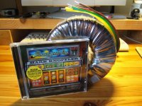
The 1000VA-er is a Plitron? i seem to see a rainbow on the label.
Times 10 is enough to need re-decorating your new nest again shortly, i see the plaster already falling down from the ceiling.
That should put my hot ladies over the 200 line on 50vac transformers and some gained volts from 75 Vdc regulation.
Actually i am a flunked car mechanic.
I do not know any transistor sizes but i know bore and stroke of every Chevrolet engine, be it road, race or baja, by heart.
The 1000VA-er is a Plitron? i seem to see a rainbow on the label.
The Transformer is from www.el-supply.dk they import the transformers them selves. Im unsure of the brand, but the tracking of the two windings is ok (within 0.5V) and there is no hum from it.
I can however hear it when I play a sinewave at full power, it sings along, but so does the resistor load that I use. I guess that is difficult to get rid of mechanical noice when the transformer is pumping 500W.
\Jens
I can however hear it when I play a sinewave at full power, it sings along, but so does the resistor load that I use. I guess that is difficult to get rid of mechanical noice when the transformer is pumping 500W.
\Jens
Thanks for the chat, Jens.
Forgot to ask you if you ever saw the site from a company in one of the former easterblock countries that sells toroids for very low prices, even huge ones ?
I'd have to look on my explorer fav. list for the name.
Forgot to ask you if you ever saw the site from a company in one of the former easterblock countries that sells toroids for very low prices, even huge ones ?
I'd have to look on my explorer fav. list for the name.
JensRasmussen said:Hi Per,
Thanks for the nice words 🙂
I have plans for a PCB order soon, but right now my financial situation doesn’t allow it (Det er jo jul).
I have uploaded the gerber data for the small version also
\Jens
Hi Jens..
Most excellent work!!
Where do you get your pcbs done...which package(s) do you use..?
Cheers!
I use Elprint (www.elprint.com) they have a great software sulution called macaos where prices are calculated based on the gerber data of a design.
\Jens
\Jens
I used an older version of Eagle, V4.11. for the Leach.
A friend from work imports it.
I also use PADS power PCB and PROTEL.
It all depends on who I'm laying the PCB out for.
\Jens
A friend from work imports it.
I also use PADS power PCB and PROTEL.
It all depends on who I'm laying the PCB out for.
\Jens
..not sure your choosen SOA protection permits efficient use of available SOA from your bank of output devices... 
5 pairs can be persuaded to drive 4ohms<60deg. to nominal 55V rails....
With a triple slope SOA protection locus derated to roughly Tc~70deg., (or ~140W;adequate heatsink assumed), you could drive 4ohms<60deg., or even a 1ohm load to the supply rails without invoking protection.....no sweat...
..and..yes..i've examined your manual...
- Status
- Not open for further replies.
- Home
- Amplifiers
- Solid State
- Leach clone, pretty good looking