Yes, it was backed down to about center.
Heatsink is about 50 C now where it is hottest. I have set mental limit to about 55C and 60C as absolute limit.
The source resistors are just below 70C according to IR gun.
Heatsink is about 50 C now where it is hottest. I have set mental limit to about 55C and 60C as absolute limit.
The source resistors are just below 70C according to IR gun.
don't fret about source resistors, as long you did mount them with some clearance to pcb (2-3mm enough)
pads and traces are hefty, so no cooking of copper
now, if you have now 50-60C at top of heatsink, no other way than using Babysitter in Summer
pads and traces are hefty, so no cooking of copper
now, if you have now 50-60C at top of heatsink, no other way than using Babysitter in Summer
Yes, I think I settle for 3A bias which is close to 1.5V across source resistors. It is with 61.2 VDC. SMPS is 65V so a little more heat.
Think 3A is fine. Will let is stay with 3A for some time and check the heatsinks. It will get more air circulation when feet comes on. But then lid is closed.
Think 3A is fine. Will let is stay with 3A for some time and check the heatsinks. It will get more air circulation when feet comes on. But then lid is closed.
Seems it settles at about 54C at SIT site and 53C at MOS side. Then about 47 at heatsink outer edges.
When voltage raises from 61 to 65 bias will also raise a bit. So bias will probably end at 3.1 - 3.2 A which also seems to be the limit for this chassis with heat spreaders.
When voltage raises from 61 to 65 bias will also raise a bit. So bias will probably end at 3.1 - 3.2 A which also seems to be the limit for this chassis with heat spreaders.
Meper, how hot is the SMPS getting handling the constant 3A current draw? I’ve noticed in class A builds with SMPS’s the small transformer gets very hot.
The SMPS is original a 2kW module. But handling 2kW would require that it should be mounted to a proper heatsink. I got it downgraded a bit with a smaller transformer and it should run more efficient at 3-4A and it should be able to run at 3-4A without any extra heatsinking but I mounted it at the bottom at the chassis as mounting holes for heatsink is 4mm thread with 10mm spacing. So it fits at the bottom (I applied heat paste also). I don't expect that it get much hot. In current configuration it can give 12-15A continuos. I used a similar 36V for VFET amp which runs at 2 x 1.6A = 3.2A. I just added small heatsinks. For Lazy the heatsinking for SMPS is much better but I can take some readings when I switch from lab supply to SMPS. Then we will see.....

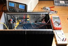
2nd mono block is up and running with 3A bias from lab supply.
Next step is to switch to SMPS. Power it up and adjust bias and DC-offset again. Then connect RCA wires and speaker binding posts......bleeder resistor etc.
That will be for tomorrow. Think I have used all my luck for today........
Next step is to switch to SMPS. Power it up and adjust bias and DC-offset again. Then connect RCA wires and speaker binding posts......bleeder resistor etc.
That will be for tomorrow. Think I have used all my luck for today........
Attachments
I now switched to the SMPS and turned on the amp where SMPS had some troubles during startup. This time it did not start at all at the first try. I traced the problem down to the large 15A Bussmann fuse onboard (Connex also pointed out that this could be the problem with the big bangs I experienced). When I measured at the fuse holders there were no connection. Then I took it out and when I pressed really hard with probes I could get connection. There was some sticky stuff on. I cleaned it and also I used a bit of 3M green scotch brite pad to be sure everything was removed. With brite pad the contact ends on fuse went from brite to a matte finish. I also cleaned the holders as good I could and tried again. Then it started up normal with 65.1 V. I adjusted the DC-offset to 32.5 VDC and also raised the bias a bit. It seems when pot is maxed out I get 3.05A which is close to 100W pr. side. About 199W in total. I think that is fine. Don't think I will raise the R2 again. But if I had a 150R that would be a better value probably. Heatsinks will probably now pass 55C......where it is hottest.
Hope it can sound good with 3.05A bias........
Hope it can sound good with 3.05A bias........
MOS-side 55.3 C, SIT-side 55.2 C. When everything is assembled with feet and lid closed I will make measurement with contact temperature probe.
Now I will see how the other amp behaves. If behaves good I will connect speaker binding posts and RCA wire. Then it is time to see if amps can handle some AC signals also. If not I have two quite expensive electrical heaters. 200W each. 400W can heat a small room.......
Now I will see how the other amp behaves. If behaves good I will connect speaker binding posts and RCA wire. Then it is time to see if amps can handle some AC signals also. If not I have two quite expensive electrical heaters. 200W each. 400W can heat a small room.......
one thing, always!!!
during setting and in general - always short input
you said RCAs are still missing....
during setting and in general - always short input
you said RCAs are still missing....
Yes, wire not connected from PCB to RCA connector.
RCA is "grounded" a "bit" via the R1 220k? .....maybe not grounded but pulled down a bit 🙂
I can take a reading again when everything is connected with RCA shorted.
Both DC-offset and bias is very stable. Only LSB digit on DMM changes -+1 from time to time after warm-up.
RCA is "grounded" a "bit" via the R1 220k? .....maybe not grounded but pulled down a bit 🙂
I can take a reading again when everything is connected with RCA shorted.
Both DC-offset and bias is very stable. Only LSB digit on DMM changes -+1 from time to time after warm-up.
all ok regarding setting, now
shorting inputs is matter of procedure/habit, to prevent possible garbage creep-in
connect everything and listen.....
shorting inputs is matter of procedure/habit, to prevent possible garbage creep-in
connect everything and listen.....
Yes, 2nd amp is on the test bench now and seems to run as 1st amp.
I will just fine tune bias to exact same as 1st amp.
Then I need to mount bleeder resistor for output cap. Binding post connections and RCA wire.
I have some thin twisted PTFE wire for that purpose.
Then I probably want to look at a sinus at scope using a small test 1000 Hz test sinus generator......and then listen.
Laster I may try making some distorsion measurements.
I think I just found out what causes the "funny" flash light and "bang" I experienced from one of the SMPSs during Startup.
It clearly came from the NTC just beside the relay. On image the "burn mark" on NTC can be seen (grey mark). So I think I need to change it. I have something similar. First I thought that it came from the relay because they are so close together. It was also an issue Connex described that such an error could occur. First time I see that.
It clearly came from the NTC just beside the relay. On image the "burn mark" on NTC can be seen (grey mark). So I think I need to change it. I have something similar. First I thought that it came from the relay because they are so close together. It was also an issue Connex described that such an error could occur. First time I see that.
Attachments

What I have is the B57364S100M.
https://docs.rs-online.com/91d1/0900766b813c0c71.pdf
When it can be used with large toriods then I assume it will work for the SMPS application also.........
It is also a 10 ohm NTC that is used in SMPS.
I will try it.......
https://docs.rs-online.com/91d1/0900766b813c0c71.pdf
When it can be used with large toriods then I assume it will work for the SMPS application also.........
It is also a 10 ohm NTC that is used in SMPS.
I will try it.......
The NTC that sits in original is a 10D-20 type. It looks a bit more "beffy".
Should I try with my?
Should I try with my?
- Home
- Amplifiers
- Pass Labs
- Lazy Singing Bush mono block build using THF51s