I have one channel up and running and applying -60V and have adjusted DC midpoint to -30V.
But it is not possible to adjust bias higher than 2.15 A or so.......then pot is turned all the way. It reacts very slowly pr. turn. I have checked that it is a 10k pot.
Is there a resistor that needs to change value to go higher in bias? ......it will be a little "fiddly" with all mounted to make changes on board......depending on where it is. Heatsinks are not getting that hot yet........about 62W pr. side with lab supply.
I think it should be possible to desolder a resistor from top and put another one in........
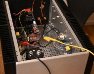
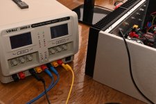
A couple of images from the initial DC-test with lab supply one mono block. The SMPS in the chassis is not connected.
It seems to run stable with 2.15A bias. It does not get more hot at heatsink then it is easy to hold hand the hottest place.
About 65W pr side.
It seems to run stable with 2.15A bias. It does not get more hot at heatsink then it is easy to hold hand the hottest place.
About 65W pr side.
Attachments

Maybe the reason I can't bias up more then 2.15 A is that I use IXTN170P10P and not the standard 40P50P ?
Then maybe the resistors around the 4N35 needs a tweak......R2 or R1 ?
Then maybe the resistors around the 4N35 needs a tweak......R2 or R1 ?
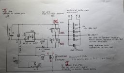
Schematic for the Mu-part is attached. The other part is just standard with components for SIT.
For Mu-part R1 is 8k2 and 0R82 and 1R2 are used as source resistors. M1 is not 40P50P but 170P10P.
I guess 4N35 transistor should conduct less to have Gate of M1 more negative to get higher bias?
So either....or both R1, R2 should have a higher value?
For Mu-part R1 is 8k2 and 0R82 and 1R2 are used as source resistors. M1 is not 40P50P but 170P10P.
I guess 4N35 transistor should conduct less to have Gate of M1 more negative to get higher bias?
So either....or both R1, R2 should have a higher value?
Attachments
After 1 hour I measured heatsinks with heat gun. The hottest side (SIT) had 49C in center and 43C at the outer part of heatsink.
Now heatsinks have bad air circulation because no feet has been installed so sinks are just standing on table. But probably about 3A bias with 65 VDC (SMPS) is about the limit for safe operation with this chassis. I can see my wish for 4A is a "no-go" 🙂 ......but 3A is fine.....maybe 3.2A 😎
Lab supply can give 5A.......but only 60 VDC......but good for an initial test.
With chassis like these I could go 4A!
https://dadbluecat.com/about-us/
Maybe it is possible to just order the chassis.......for the next project.....
https://dadbluecat.com/about-us/
Maybe it is possible to just order the chassis.......for the next project.....
If your using the rigid white ceramic pads, goop is necessary between heatsink/pad and pad/SIT.I have got the heat transfer/isolation pads from Watanabe who sold them Tokins. Do you have these pads and? And are we also supposed to use cooling paste with them?

Yes, so far so good.
I think the "bias problem" is because there are so many configurations so it is easy to mix something up 🙂
With the component used I think circuit behaves as expected.......but we will see......I will get more information 🙂
So far my guess is that the "secret" are in the values for source resistors.......how high bias you can get.
There has been some "confusion" about which source resistors to use......5 x 1R, 3 x 0R82 etc.......but to get the ratio of 0R2 and 0R3 I just need to insert one more of each resistor so I have 4 x 0R82 and 4 x 1R2......and then try again with pot set back to center. This will be tomorrow.
There is mentioned 220R 3W shunt resistor at speaker terminals.
Is that for bleeding the output cap?
When connected to my speakers the woofer is DC-coupled but could be used in a bi-amp configuration.
So I should probably mount them?
I found 270R, 2.5W. I guess these can be used......
Is that for bleeding the output cap?
When connected to my speakers the woofer is DC-coupled but could be used in a bi-amp configuration.
So I should probably mount them?
I found 270R, 2.5W. I guess these can be used......
Attachments

When connected to my speakers the woofer is DC-coupled but could be used in a bi-amp configuration.
clarify
when speaking of Lazy, no speaker is DC connected to it ........ output cap is always in the game
I don't care for your xover, if you're speaking about that (woofer)
said resistor is intended to be connected across amp speaker terminals ....... and yes, that's output cap bleeder

Yes yes, I meant woofer + xover is maybe 6 ohm DC resistance when connected.
I will mount the bleeder resistor then cap will bleed at all circumstances.
I wonder about bias when I put in the extra source resistors in. Then I have 0.5 ohm in total.
The max. voltage I could get across the 0.67 ohm (as is) was about 1.44 V. With 0.5 ohm this will give 2.8 A.
But maybe "other things" will cause that bias goes higher......e.g. less current through diode of 4N35 because voltage will be less across it caused by the extra source resistors........it is probably so.
I've told you about R2, easy to dial in
bleeder resistor is there to ensure cap bleed even in cases when speaker is disconnected
and it happens that speaker is sometimes disconnected and amp is powered on without speaker
bleeder resistor is there to ensure cap bleed even in cases when speaker is disconnected
and it happens that speaker is sometimes disconnected and amp is powered on without speaker
Ok, I have 121R in stock which will give 20% more.....if there is a linear relation with small changes. It should be sufficient.
With changes it bias up to 2.93A with -60VDC (pot centered). It is about 90W pr. side.
Will see how hot it gets. The nominel bias for this configuration is 3.2A ?
I have rail fuse = 4A F.
Will see how hot it gets. The nominel bias for this configuration is 3.2A ?
I have rail fuse = 4A F.
slightly increase R2, to get to desired Iq; don't forget to back down with Iq, prior to change, then set it again
3A2 isn't carved in stone, but why not; parts will be happy, as long heatsinking is suficient
3A2 isn't carved in stone, but why not; parts will be happy, as long heatsinking is suficient
- Home
- Amplifiers
- Pass Labs
- Lazy Singing Bush mono block build using THF51s