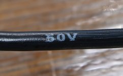
From cellar approx. 3m left of vintage 2.5mm2 cable. It fits into the large holes on PCB and just into the output cap holes.
Cable is 50V rated which in principle is not enough for a 65V application. I guess in practice not a problem but it will be easy to just get other cable with correct ratings.
Cable is 50V rated which in principle is not enough for a 65V application. I guess in practice not a problem but it will be easy to just get other cable with correct ratings.
Attachments
Ok, then I will use what I have.
The money I saved I just spend on an offer of 6 bottles of 2015 Amarone della Valpolicella Riserva.........
The sum of "abuse" is constant......
The money I saved I just spend on an offer of 6 bottles of 2015 Amarone della Valpolicella Riserva.........
The sum of "abuse" is constant......

The Amarone is 16.5 Vol(t)!
https://www.boscainicarlo.it/eng/pr...della-valpolicella-docg-classico-riserva.html
https://www.boscainicarlo.it/eng/pr...della-valpolicella-docg-classico-riserva.html
Regarding the 50V branding the closets I could come to regarding data sheet from NKT is this:
https://nkt.widen.net/content/ipkqtvtaav/pdf/PVTAU_MonteringsledningAPP_LV_DS_DA.pdf?u=gj0n1y
It seems the 50V branding is AC. So < 75V DC .......then I am safe and can get good nights sleep again. Maybe even better after a bottle of 16.5 Vol(t) Amarone.......don't know if the 16.5 is AC or DC......
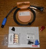
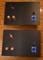
One of the next steps is to work on the back panels. RCA, Speaker terminals, power connector etc. have to be mounted.
Earlier there was a discussion on how to make a square hole for an IEC connector. I decided to got Neutrik PowerCon for an easier to make round hole. Same hole size as for the RCA connector which is also Neutrik. I have done that before using a 24mm hole-saw. It goes like butter through the aluminium. I don't need a power on/off switch for the amps as I have one central place to power it all on/off. For VFET amp I also bypassed the mains power switch on back panel. Often these switches feels a bit "flimsy". Not very high contact pressure?
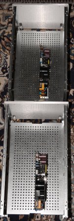
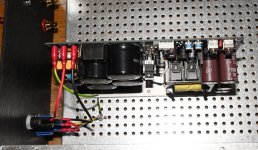
SMPS's have been installed in both chassis. Soon they will start look like amplifiers.
I like the PowerCon mains cables.......1.5mm2 wires! lifetime warranty! 16A rated!
Earlier there was a discussion on how to make a square hole for an IEC connector. I decided to got Neutrik PowerCon for an easier to make round hole. Same hole size as for the RCA connector which is also Neutrik. I have done that before using a 24mm hole-saw. It goes like butter through the aluminium. I don't need a power on/off switch for the amps as I have one central place to power it all on/off. For VFET amp I also bypassed the mains power switch on back panel. Often these switches feels a bit "flimsy". Not very high contact pressure?
SMPS's have been installed in both chassis. Soon they will start look like amplifiers.
I like the PowerCon mains cables.......1.5mm2 wires! lifetime warranty! 16A rated!
Attachments

When it comes to the bias adjustment procedure is there a post# in original Lazy thread to look at?
I am not there yet......but good to be prepared.
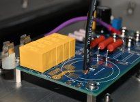
For SIT bias I guess I measure voltage over MOSFET source resistors at Mu-PCB. In my case with 0R82 x 3 and 1R2 x 3 is about 0R67 in total. If I go for about 2V to begin with by adjusting P1 I can check how hot everything gets and take decision from there.
Then we also want about U/2 at output cap? .....in my case -65/2 = -32.5 V?
P1 at input JFET PCB is used for that purpose?
There is mentioned 11mA bias though JFETs. Should I check that bias by looking at voltage over R8?
I am not there yet......but good to be prepared.
For SIT bias I guess I measure voltage over MOSFET source resistors at Mu-PCB. In my case with 0R82 x 3 and 1R2 x 3 is about 0R67 in total. If I go for about 2V to begin with by adjusting P1 I can check how hot everything gets and take decision from there.
Then we also want about U/2 at output cap? .....in my case -65/2 = -32.5 V?
P1 at input JFET PCB is used for that purpose?
There is mentioned 11mA bias though JFETs. Should I check that bias by looking at voltage over R8?
When it comes to the bias adjustment procedure is there a post# in original Lazy thread to look at?
I am not there yet......but good to be prepared.
For SIT bias I guess I measure voltage over MOSFET source resistors at Mu-PCB. In my case with 0R82 x 3 and 1R2 x 3 is about 0R67 in total. If I go for about 2V to begin with by adjusting P1 I can check how hot everything gets and take decision from there.
Then we also want about U/2 at output cap? .....in my case -65/2 = -32.5 V?
P1 at input JFET PCB is used for that purpose?
There is mentioned 11mA bias though JFETs. Should I check that bias by looking at voltage over R8?
dunno for biasing procedure post - check
anyhow, connect everything as needed, observe voltage sag across power resistors, do the math U=Iq*R, so you know what figure to chase
fine tune of Iq goes with trimpot on Mu pcb
setting output node voltage level (inside of output coupling cap) to approx. rail/2 goes with trimpot on gain pcb
Iq of buffer cell is predefined; as matter of curiosity, check that you have approx. 0V65 across R8 there
posts #1 and #2 of https://www.diyaudio.com/community/threads/lazy-singing-bush.388164/
Thank you!
It sounds easy.
The project will be delayed a bit as I tested the two SMPS's today after I finished the back panels.
One SMPS works as expected while the other starts up with a big bang. I see a flash light from the "soft start" relay immediately after mains power on.
Apart from that it works. 65V at output. I loaded it with 16 ohm for a short time. I need to contact the company (Connex) as I got it directly from them. I guess they may have a theory what goes wrong. The relay should kick in a short time after power on and short the NTC. Also I had a 2A T mains fuse which burned. I guess this should not happen is soft start was working. A shame as I have some days off work so I had time to finish the project......but that is how it is.
After all I am quite close.....I could finish one amp but I want to be sure I can get a spare SMPS or maybe I can be guided to fix it. At least I think a new relay is necessary as it may have some burned contacts.
Attachments

Darnit! Murphy must have built one of your new power units 🙃
Well that will give you more time to build all the rest slow and good while you wait for the new PSU. Dont cheat and listen to just one channel like they did way back in the stone age!

Well that will give you more time to build all the rest slow and good while you wait for the new PSU. Dont cheat and listen to just one channel like they did way back in the stone age!
There are not much rest to be built. Next step would be installing of output cap and after that I would mount the heatsink panels. And then only a few wires needed to be connected before bias adjustment.
I wait until I hear from Connex with a solution. They I may finish one channel 🙂
Probably if I removed the softstart relay it would work. Then the NTC resistor would be in the line all the time. I think only purpose for relay is to short the NTC after a few seconds.
What I am not sure about is if I still had a few seconds before 65V showed up on DMM like on "good" unit. If not this would be a final conclusion that soft stat does not wok. I guess Connex should have good experience with the behavior. Would be strange if I was the first to experience this. Maybe they will guide me to do "something". The "turn-around" time from here to China and back is quite long.......
It is 2 x SMPS2000RS modules with 65V output. They where modified with a smaller transformer as I don't need 30A output. Then it can run more efficient and with lower noise.
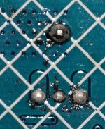
I compared by looking at fotos components between the two PSU's to see if I could find any differences. Was looking for something that could cause the delay circuit not to function correct by trigger immediately. I have no idea how it is designed. Often a transistor is involved in such a circuit that controls the current through the coil of the relay. I can see a small power transistor (think it is) where there are some dirt between the solder pads. I wonder if this could cause the circuit to trigger immediately.......but it is a wild guess that this transistor is involved in the delay circuit. I should probably clean it anyway........
It is clean on the good board.
It is clean on the good board.
Attachments
- Home
- Amplifiers
- Pass Labs
- Lazy Singing Bush mono block build using THF51s