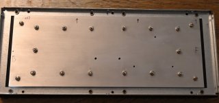
I am preparing a bit for the next steps. All holes / M3/M4 threads are finished so panels are almost ready to be mounted permanet to heatsinks with heat-paste and screws.
After solder components to PCBs I am looking at mounting the big MOSFET/SITs. IXYS provide the mounting specification attached. They specify max. mounting torque at 1.5 Nm for base and 1.2 Nm for terminals. Do you all have ISO calibrated torque wrenches for this job (and get them calibrated regulary)? ......or do we just use "common sense" when mounting these components? ......I have used "common sense" so far for my builts. But maybe I have an excuse to get more fancy tools? 🙂
I have looked at some torque wenches which mostly are prized rather high (Wiha, Wera, Gedore etc).
E.g. Wera makes a nice one (green) then they make one which looks exactly the same but almost double prized. The reason is the yellow is ESD-certified. This could be nice when it is for electronics?
Wiha also makes a "yellow"......it seems this color is used a lot for ESD-tools.
Attachments
I got tempted and ordered this ESD Wiha:
https://www.conradelektronik.dk/p/w...61340-5-1-din-en-iso-6789-din-en-26789-283585
It can go from 1 - 5 Nm. So everything I do from now will get at least 1 Nm of torque.
https://www.conradelektronik.dk/p/w...61340-5-1-din-en-iso-6789-din-en-26789-283585
It can go from 1 - 5 Nm. So everything I do from now will get at least 1 Nm of torque.
well, 0.9Nm is prescribed value for most of M3
most critical being Keratherm 86/82, which is best to not overtighten or it will squish too much on screw side
anyhow, I believe you're good with 1Nm for that, close enough
for M4 hardware, just follow what you read in part datasheet
I ave 2 thingies - fixed ones
I did calibrate one for 0.9, other to 1.2Nm
handy to have, less thinking
Yes, for chassis etc. not an issue and I have never until now using normal screwdrivers for electronics damaged any components. But I just thought now I invested in a torque wrench I invested in the ESD one. A little more expensive but then I may sleep better in the night 🙂
I wonder if it is the "click" when torque is reached that can introduce a static charge in "non-ESD" wenches.
I wonder if it is the "click" when torque is reached that can introduce a static charge in "non-ESD" wenches.
Now I also ordered the ESD Wiha torque handle which goes from 0.4 - 1 Nm.
So I guess I have what is needed for most of my applications.
So I guess I have what is needed for most of my applications.
I agree.......but now that it was a "once in a lifetime" investment.......I selected the yellow handles.
It can be fun to google if ESD tools are necessary or not......lot of opions......as expected.
Until yesterday I did not know the "ESD concept".
It can be fun to google if ESD tools are necessary or not......lot of opions......as expected.
Until yesterday I did not know the "ESD concept".
A couple of pictures after first panel has been attached to heatsinks. Surfaces were degreased and then a thin layer of heat paste was applied.
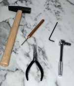
Also a picture of the tools used for this process!
The hammer and punch tool was to give the hex screws a small "punch" to get it "though" the ribs. The space between ribs decreases from top to bottom. If holes are centered perfect a very small "knock" was enough. It was not necessary to change size of hammer for holes which were not 100% centered! I used this easy method instead of file the screw heads a bit. It was a lot easier than expected. The plier used as pincet to place the screws and wrench and hex-key to fasten the screws. Think I understand why through holes are necessary.
Attachments
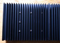

I hope so. The other four screws in the corners are just to positioning the panel which helped a lot. M4 threads was made in heatsink for this purpose. Then I hope for good thermal contact made by the "through holes" screws so bias can be cranked up at least 0.5A more than "expected" 🙂
Now all four panels has been attached to the heatsinks. Next step is stuffing the PCB with components and solder them.
I have looked at the two schematics and also looked into the kit components. I remember that the large output cap and source resistors were not part of kit. Source resistors should be 10 x 1R 3W MOX pr. channel. I am going to order these.
I found some power resistors in the kit which "smells" a little bit like source resistors. Some 1.2R 3W and some 0.82R 2W ?
If I mix them there could be enough for two channels (20 are needed).......?
Attachments

you got everything, regarding Mu Follower resistors, no need to buy them
re-read the thread, and you'll see
I started with 5+5 of 1R, later changed to Ben Mah's recipe
re-read the thread, and you'll see
I started with 5+5 of 1R, later changed to Ben Mah's recipe
I found this:
"Following Ben Mah's findings, about 3:2 Mu resistors ratio, and counting that same applies to 2SK2087C, be it combined with puck or IRFP, that would be 3*1R2/3W MOX at Mu MOS Source side, and 3*0R82/3W MOX at SIT side
so, 400mR + 273mR
resulting in sum of 673mR, pretty close to desired sum of 666mR
clearer:
R5,7,9 being 1R2/3W MOX
R4,6,8 being 0R82/3W MOX"
Below there is a schematic. I have saved the schematic and will print it later........
so, there you have it
you have enough 1R2 and 0R82
and don't fret smaller ones being 2W, there is no more than 820mW on each, even in case of 3A for Iq
P=I^2*R
so, 3^2*(0R82/3)=2W64 ........ that being 2W64/3=820mW for each
solder them 3mm above pcb and all good
you have enough 1R2 and 0R82
and don't fret smaller ones being 2W, there is no more than 820mW on each, even in case of 3A for Iq
P=I^2*R
so, 3^2*(0R82/3)=2W64 ........ that being 2W64/3=820mW for each
solder them 3mm above pcb and all good
Yes, thank you. I will solder them above PCB. Will start with the small parts.
Will check thread if there are changes also for the other PCB. Before I start I will try to match all components in the kit.
I know there are some SIT specific values for diodes, resistors. I will mark these on schematic so I avoid such a mistake.
Will check thread if there are changes also for the other PCB. Before I start I will try to match all components in the kit.
I know there are some SIT specific values for diodes, resistors. I will mark these on schematic so I avoid such a mistake.
The voltage set by P1 (SIT part) is that approx. 1/2 rail voltage?
So -30 V for -60 V ail and -32.5 V if rail is -65 V (which will be my case)?
The other P1 at Mu part which sets the Iq (or fine tunes it). To preset this pot to have less Iq I need Vg at SIT less negative to Vs?
Then I need to set pot so it acts like a 10k resistor.....then Vg will get less negative? ......if shorted Vg gets closer to U-?
What does A*2, S*2, E*2 related to trim pots mean?
No hits using Google 🙂
I have not soldered anything yet.......just preparing.
A2,S2,E2, are residual of Eagle pcb program, in fact of trimpot part package in Eagle
it is actually first time I even see those letters, always ignoring them
yes, Iq is set in Mu part of amp
output node voltage (rail/2) is set by trimpot in SIT part of amp
no need to preset any of these trimpots ( usually they're somewhere at 50% from factory, but really irrelevant)
just clunk power on, observe with DMMs what needs to be observed and set what needs to be set
Ok, I will check that the trim pots are approx. centered.
I have a 2 x 0-30 V lab supply where I can combine it to a 60V / 5A supply. I will start with that......set it to maybe -40V and with current limiter and see what happens.
I wonder if the 4n35 does not work (or if not inserted) if bias will go "bananas"......not that I will try it.......
I have a 2 x 0-30 V lab supply where I can combine it to a 60V / 5A supply. I will start with that......set it to maybe -40V and with current limiter and see what happens.
I wonder if the 4n35 does not work (or if not inserted) if bias will go "bananas"......not that I will try it.......
- Home
- Amplifiers
- Pass Labs
- Lazy Singing Bush mono block build using THF51s