
Today the two 65VDC PSUs arrived. Those where special order as 65V was not standard.
Originally the modules are 2kW but company used another transformer as I only need about 4 A. It is made for max. 10-12A. Then noise performance and efficiency will be better.
Here is what the company wrote after they asked for what the usage was for (fine service):
"I see now, if you are only gonna use around 4A (10A peak or so) we can optimize the transformer and the overall design for a lower current which will increase the efficiency, reduce temperature rise and noise.
As you might know, any SMPS optimal operating point where the efficiency peaks and noise is lowest is around 50-60% of the rated power, in this case about 1000-1200W while at extreme low and extreme high, the efficiency suffers. At low power, there are idle or quiescent losses which are proportional with the maximum power, usually 1-2% of the max power, and by reducing the max power will get the optimal operating point closer with your actual usage scenario.
The SMPS will be the same, but to optimize these parameters we can set the maximum current to approx. 12-14A focusing on efficiency increase and noise reduction and if your load is just 4A it can work with minimum cooling requirements."
What is pure luck is that the 6 x M4 mounting threads in the heatsink has spacing of 10mm multiplums so in the be mounted easy on base plate which is my plan. The heatsink is not connected to Gnd internally on PSU which would cause troubles as I need -65V so PSU Gnd will be -V. There is a resistor in serie with a very small cap to protect the devices against static charges.
while working on assembly and initial setting, best to have temporary fuse inserted in rail, 4A or so
when everything done, remove it
when everything done, remove it
Yes, the idea was to have a 4A F as permanent fuse just for safety.
Also if I put a couple of large caps at the output (for extra filtering) of the PSU then the 4A F will be after the caps.
I have a similar type 36V PSU for the VFET amp (which has a 30A fuse on board) and then large extra caps and then the smaller fast fuse for safety.
Also if I put a couple of large caps at the output (for extra filtering) of the PSU then the 4A F will be after the caps.
I have a similar type 36V PSU for the VFET amp (which has a 30A fuse on board) and then large extra caps and then the smaller fast fuse for safety.
Hi Meper,
which brand did you choose for your SMPS? Thanks
Have fun building your nice amp, I'm curious on your decisions and will follow your thread.
which brand did you choose for your SMPS? Thanks
Have fun building your nice amp, I'm curious on your decisions and will follow your thread.
The SMPS are Connex SMPS modules. Original made for class D amps:
https://connexelectronic.com/product-category/power-supplies/
Look for the SMPS2000 modules. The 2kW modul exists in single and dual voltages and they can be ordered with a custom voltage.
E.g. 60V is standard. I ordered 65V for the Lazy Bush (voltage can be adjusted -+ 10% or so).
I god my downgraded a bit in power to better fit to my needs. It was a bit difficult to find a shipping carrier for two modules from China but succeeded perfect with DAO to a packet shop just 3-400m from where I live.
Audiophonics in France also sell Connex:
https://www.audiophonics.fr/en/search?search_query=Connex
I guess a custom voltage can be ordered via them so they have all the trouble with shipping. The Covid situation i China did not help as there were lock downs during the production of the SMPS so it was difficult to get the right transformer. But they are nice people at Connex. They responded to every mail I sent. Also last time I got a Connex SMPS via Audiophonics for the VFET amp I asked Audiophonics about the quality and they responded that they have had a fine relationship for many years without problems with quality.
A pdf here with description and noise measurements etc.:
http://connexelectronic.com/wp-content/uploads/2017/04/SMPS2000RxE.pdf
http://connexelectronic.com/wp-content/uploads/2017/04/SMPS2000RxE.pdf
Wow, thank you a lot for your detailed answer and your experiences with Connex! Thank you very much Meper!
A small update for the "lazy project".
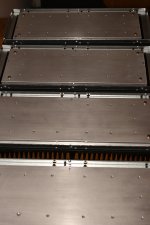
"Through holes" has been drilled in panels and heatsinks.
The four M4 screws in the corners are just to "hold" the panels in place which I think helps a lot. M4 threads are cut in heatsinks for this purpose.
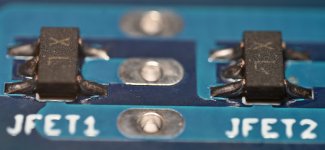
Next step is to drill holes and cut threads for PCBs and THF-51s.
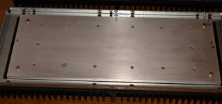
I will make two identical mono blocks. I will not mirror........
I have marked everything so same panel and sinks belongs to each other. When holes are drilled free hand etc. they are not placed 100% same place so panel and sinks belongs together as a set and also the frame........just in case.....
I need to read the "Lazy thread" before I mount components so I am sure I do it right. There are many yellow MKTs 🙂 ......and a few red ones 🙂
I also need to know the melting point of aluminium before I crank up the bias for the final adjustments when everything are finished........
Then we can go for melting point minus 100C or so.......better safe than sorry......
"Through holes" has been drilled in panels and heatsinks.
The four M4 screws in the corners are just to "hold" the panels in place which I think helps a lot. M4 threads are cut in heatsinks for this purpose.
Next step is to drill holes and cut threads for PCBs and THF-51s.
I will make two identical mono blocks. I will not mirror........
I have marked everything so same panel and sinks belongs to each other. When holes are drilled free hand etc. they are not placed 100% same place so panel and sinks belongs together as a set and also the frame........just in case.....
I need to read the "Lazy thread" before I mount components so I am sure I do it right. There are many yellow MKTs 🙂 ......and a few red ones 🙂
I also need to know the melting point of aluminium before I crank up the bias for the final adjustments when everything are finished........
Then we can go for melting point minus 100C or so.......better safe than sorry......
Attachments
OK, the big puck MOSFET is secured by screws and the THF-51s I can screw / crimp the connections for the wires so I avoid thinking of solder melting point.......which I suspect is lower than for aluminium 🙂 .....I use PTFE isolated wires.....but maybe naked wires sounds better.
do-not-crimp-!
if there is plastic sleeve on thingies, remove it (hot gun, lighter, whatever), crimp wire just slightly to keep it place, them solder wire in thingie
heatshrink in appropriate color, Voila!
if there is plastic sleeve on thingies, remove it (hot gun, lighter, whatever), crimp wire just slightly to keep it place, them solder wire in thingie
heatshrink in appropriate color, Voila!
Ok.....but I have a very nice (and expensive) Knipex crimp tool 🙂 .....and "crimp shoes" with copper rings that will harden with presure.......but I will solder and then maybe settle for a little lower heat sink temperature.......
I read an article written by Nelson Pass about "leaving class A" ........but I think I will never leave class A.......
I read an article written by Nelson Pass about "leaving class A" ........but I think I will never leave class A.......
nothing wrong with mild !KlunK!, here and there
though, with SE amp, hard to get outa A class ...... if we exclude clipping

though, with SE amp, hard to get outa A class ...... if we exclude clipping
If is clips.......something went very wrong........
Regarding a good output cap it seems I am forced.......more or less to use an E-CAP for the most of the mF's........
I am looking at this one:
https://www.mundorf.com/audio/en/shop/capacitors/power_caps/mlytic_ag/MLytic-AG/?card=2501
It is 10 mF / 80V DC with 10mm pin spacing (it is not the correct one they picture at the link).
Is there a better alternative?
I need to find a seller as I can probably not get them directly from Mundorf.
I know that Mundorf does not make them but have FTCAP to make their E-CAPS so maybe money can be saved by finding a FTCAP branded version instead?
https://www.ftcap.de/en/
FTCAP is now "MERSEN"........strange world.......
don't fret too much about cap voltage
even 50V cap will never see 50V across terminals, in Lazy
think
so, feel free to use 63V
and, it is heavily bypassed with MKC ........ you don't need fancy name, just proper industrial quality
even 50V cap will never see 50V across terminals, in Lazy
think
so, feel free to use 63V
and, it is heavily bypassed with MKC ........ you don't need fancy name, just proper industrial quality
Perfect, I just think I read min. 75V DC in "Lazy thread" so I thought it could be a "start-up" condition that could cause high voltage on cap (close to PSU voltage). But with 65 VDC PSU even a 63 VDC cap would not break.
I have nice 63 VDC screw-mount caps. I may use these and place them close to PCB so wires from cap to PCB gets as short as possible.
The large screw mount types has much lower ESR and much higher ripple performance when I look into datasheets for these types of caps. Then I am not limited by the max. 35mm diameter size for PCB mount.
- Home
- Amplifiers
- Pass Labs
- Lazy Singing Bush mono block build using THF51s