Hi,
@denbret: How is the power supply designed in your L12?
I liked to use those little 6x10.000µF modules together with a >200VA toroid and I certainly cannot attest flat soundstage, thin sound or lack of Bass.
I also modify my amps slightly -rather because of a good gut feeling than expecting real sonic improvements- but maybe this helps a bit too.
jauu
Calvin
So before deciding on what preamp I will hook to it, I ordered the P7 mini Free shipping NEW P7 MINI Preamplifier Board Top Pre AMP Headphone DIY Kit for MX50 L20 L6 NE5532 High quality|kit diy|kit kitskit headphones - AliExpress
This raises a question. In France the power is 235V so my 220V to 12V outputs roughly 15.3V
The P7 mini runs on 12-0-12V.
My switching power supply has a. 12+ - DC output.
Can I bypass the rectifier and hook the DC to +and - after the DB107?
Thanks
This raises a question. In France the power is 235V so my 220V to 12V outputs roughly 15.3V
The P7 mini runs on 12-0-12V.
My switching power supply has a. 12+ - DC output.
Can I bypass the rectifier and hook the DC to +and - after the DB107?
Thanks
235 V is +6.8% over 220. 15.3 V is 27.5% over 12. So the problem is definitely not the difference of 235 vs 220 V. Could the voltage be higher than spec because you're measuring without load?In France the power is 235V so my 220V to 12V outputs roughly 15.3V
235 V is +6.8% over 220. 15.3 V is 27.5% over 12. So the problem is definitely not the difference of 235 vs 220 V. Could the voltage be higher than spec because you're measuring without load?
You are totally right, I measured without load... I didn't think it would make a difference 😅
I guess I am in business then.
Hi,
@denbret: How is the power supply designed in your L12?
I liked to use those little 6x10.000µF modules together with a >200VA toroid and I certainly cannot attest flat soundstage, thin sound or lack of Bass.
I also modify my amps slightly -rather because of a good gut feeling than expecting real sonic improvements- but maybe this helps a bit too.
jauu
Calvin
No lack of bass on mine with switching power supply. The basse is really strong and the soundstage quite wide. It is a very analytic but Can get fatiguing, that is why I am looking for thé right preamp
Thank you for your write-up on this amplifier and the detailed description of the mods!I also modify my amps slightly -rather because of a good gut feeling than expecting real sonic improvements- but maybe this helps a bit too.
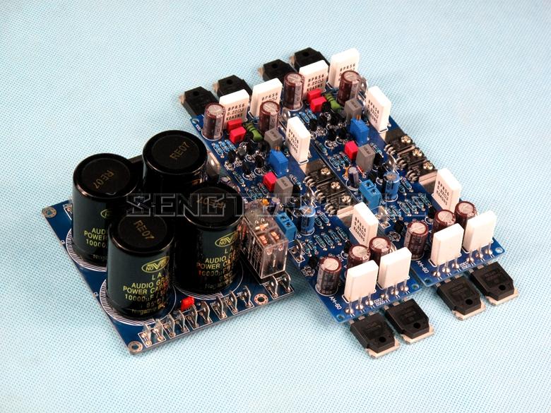
Received my pre-assembled boards, they look fine (to my inexperienced eye). One board could use a little cleaning of the back side, the other one looks pretty clean as is. Are they poorly assembled? I'm not seeing anything bad except for some junk tangled in the legs of the power transistors, looks like the snipped-off remains of some other components' leads. Very easily removed, but could be a disaster if you miss it.
Here are the photos.
Here are the photos.
It appears that there is new, improved version of L12-2.
AM 60 HIFI Stereo ON0302 0281 Amplifier Board Rectifier Board+Power Amplifier Finished Board|Amplifier| - AliExpress
Now, the board has:
1. potentiometer for quiescent current adjustment,
2. power supply and speaker protection,
3. KEC output transistors are replaced with ON NJW0302/NJW0281.
This is gnificant improvement over the old version. 🙂
Attachments
The datasheet says that heatsink is connected to the collector for both of these transistor models. And collectors are already connected on the schematic, so it's okay to bolt them directly to the heatsink pair-wise. But not okay to connect 2837 and 1186 together on the same heatsink because there is supposed to be a 0.22 Ohm resistor between each of them and the output (0.44 in total). Guess this is why I received a set of thermal pads with each amplifier - glad I won't have to source mica pads.
By the way, what's the purpose of this resistor (R13/R20)? Doesn't it automatically increase the output resistance by 0.22 Ohms, which is quite bad for a power amplifier - damping factor less than 18 at 4 Ohm load?
By the way, what's the purpose of this resistor (R13/R20)? Doesn't it automatically increase the output resistance by 0.22 Ohms, which is quite bad for a power amplifier - damping factor less than 18 at 4 Ohm load?
Last edited:
Hi,
##690 why or what should be the ´significant´ improvement?
Rather looks like just another shameless clone with output transies with higher capacitances than the originals.
jauu
Calvin
##690 why or what should be the ´significant´ improvement?
Rather looks like just another shameless clone with output transies with higher capacitances than the originals.
jauu
Calvin
Hi,
R13 is the emitter resistor of the ´quasi´ NPN transistor Q5/(Q2,Q10) and R20 the emitter resistor of the ´quasi´ PNP-transistor Q9/(Q14,Q18).
The output impedance is mainly defined by feedback action and alot lower than 0.22R.
jauu
Calvin
R13 is the emitter resistor of the ´quasi´ NPN transistor Q5/(Q2,Q10) and R20 the emitter resistor of the ´quasi´ PNP-transistor Q9/(Q14,Q18).
The output impedance is mainly defined by feedback action and alot lower than 0.22R.
jauu
Calvin
Hi Calvin, thank you very much for the reply.The output impedance is mainly defined by feedback action and alot lower than 0.22R.
I understand my question is about electronics in general and not about the L12-2, but I genuinely don't understand something here. The emitter resistors are in series with the load (amp's output), aren't they? And it's not possible for the total impedance to be lower than its active component (in this case 0.22 Ohms). Or is it?..
An unrelated question: is it OK to test L12-2 with +/-24 DC voltage supply? Should I expect degraded performance or not? I mean performance in terms of THD and such, not the peak output power, obviously. From the power standpoint, +/-24 V should already give me more than I'll ever need.
Last edited:
Hi Calvin, thank you very much for the reply.
I understand my question is about electronics in general and not about the L12-2, but I genuinely don't understand something here. The emitter resistors are in series with the load (amp's output), aren't they? And it's not possible for the total impedance to be lower than its active component (in this case 0.22 Ohms). Or is it?...
Yes, but don't forget those emitter resistors are inside feedback loop. Total output impedance is then defined by feedback factor and much lower than 0.22R
Thanks, I actually missed that, makes sense now!those emitter resistors are inside feedback loop
Hi all. I have a couple of questions about the LJ12-2 that I can't find the answer to in my (sorry) not totally thorough look through the 70 odd pages of this thread. I am about to buy 8 of these amplifiers. Cases, power supply, everything else is ready for them, but I don't wan't to make a big mistake with these.
Firstly, is there a more genuine/bona-fide outlet to buy these amps than Aliexpress or Banggood please?. I'm assuming there is such a thing as a genuine LJM and the CN versions are not that.
Second, can somebody with a board please measure for me the pitch between two adjacent power output transistors as accurately as you can?. I'm lucky to have enough genuine OnSemi MJL4281A/MJL4302A to do the job, but they look just slightly too big. They are TO-264 and measure 20.0mm wide. The leg to leg pitch of both is 0.215inch (5.45mm) which is good. The TO-3P-3L devices supplied are 15.6mm wide, and from photos seem to be on 0.75inch(19.05mm) pitch on the board. If they are, it will be a bit of a squeeze to fit the MJL's. An accurate number on the actual device pitch would be useful to know please.
If I do fit the MJL's I am inclined to stay with OnSemi and fit MJE15034/5 drivers and MJE340 bias transistor, purely because I know them and like their voltage rating and linear hfe.. I'd like any opinions on that please.
I think the two versions, class A or AB is a myth, yes?. the bias current is easily to set to what you want by varying R19.
Many thanks.
I've seen mentions of the store on TaoBao that is supposedly run by LJM himself. But that post is from a number of years ago, I haven't checked if that store / link is still operational.
- Home
- Amplifiers
- Solid State
- L12-2 CFP Output amp 120W*2 8R